Steel Truss Design to Eurocode 3
![[object Object]](/_next/image?url=%2Fimages%2Fauthors%2Fcallum_wilson.jpg&w=256&q=75)

Welcome to the third article in our series on steel design using Eurocode 3. After part 1 and part 2, you should be familiar with how to use the Eurocode 3 document (well, part 1-1 at least!), so we won't spend any time re-introducing the document. The tutorial is structured into the following sections:
✅ Section 1: Trusses as a Structural System
In section one we introduce the truss as a structural system and discuss some common use cases. This is a short section because much of this introductory material on trusses has been covered in our previous tutorials (referenced in the section).
✅ Section 2: Truss Analysis
Section two is again pretty short because we’ve covered various methods of truss analysis in our previous tutorials. We'll point out the relevant tutorials in this section, in case you need to brush up on your truss analysis skills before moving on to design.
⏩ If you’re already familiar with trusses and how to analyse them to determine member forces and deflections, jump straight to section 3 where we get into the design process using Eurocode 3.
✅ Section 3: Steel Truss Design Process to Eurocode 3
When designing the individual elements within a steel truss, we will either design for compression or tension. We’ve already discussed (in great detail) designing for compression in part 2.
So, in this section, we’ll very briefly recap the overall compression design procedure and introduce the significantly simpler tension design procedure. We’ll also point out a couple of other important considerations in the design process.
✅ Section 4: Steel Truss Design Case Study
Section 4 is where the learning happens! We’ll set out a pretty common design scenario - the design of a steel roof truss arranged in the classic Pratt configuration.
We’ll walk through the complete design procedure, from a simple load takedown to developing load cases and ultimately designing the truss to satisfy both ultimate and serviceability limit states. By the end of this section, you should be comfortable independently developing code-compliant truss designs.
✅ Section 5: A Simplified Approach to Steel Truss Design
Full detailed design isn’t always required - especially at the start or scheme design stage of a project. So, in section 5, we’ll cover some methods for approximately determining the appropriate size of truss elements.
✅ Section 6: Coming up next!
In the final section, we’ll announce our next and final destination on this steel design journey!
1.0 Trusses as a Structural System
Before we open up Eurocode 3, let’s first discuss trusses as a structural system and make some observations about their strengths and weaknesses.
1.1 What are trusses?
For a complete introduction to trusses, take a look at this tutorial. For the purposes of this tutorial, we’re just going to summarise the key features of this important structural form.
-
A truss is a structure that consists of a collection of elements or members connected at pin joints or nodes.
-
In theory, the pin joints provide no rotational resistance and behave as hinges, in practise the rotational stiffness of the joints depends on the type of connection used.
-
The major benefit of a truss is that the members are predominantly axially loaded. We know that axially loaded members can be very efficient since the uniform stress distribution across the section evenly utilises the full cross-section.
-
Trusses are a very well understood structural form and have been in use for hundreds of years. Some common forms were popularised in the 18th century and typically bear the names of the engineers that first developed them - Pratt, Howe, Warren to name just a few.
1.2 Typical truss applications
As we’ve already said, trusses are an incredibly efficient and lightweight structural form. Because of this, we often find steel trusses deployed in the following applications:
-
Bridges
-
Transfer structures in high-rise construction
-
Proprietary scaffolding products such as lattice beams
-
Long-span roof structures, particularly in sports stadiums
-
Outrigger elements in super high-rise construction
1.3 Special considerations when designing trusses
A key observation we can make regarding trusses is that, structurally, they can be thought of typically as 2D structures (3-dimensional trusses are often referred to as spaceframes - we discuss their analysis here). Unlike a traditional steel beam, which has a defined major and minor bending axis, a standard truss only really has a major bending axis. A truss is typically designed to resist bending about the major axis only. With that said, we need to be aware of the following factors when specifying steel trusses:
-
Any out-of-plane loading, i.e. loading normal to the plane of this truss, which causes bending about the minor axis, must be carefully considered.
-
Load reversals e.g. caused by wind uplift could cause tension members to experience compression and vice versa. This is not necessarily a big problem but is a factor which needs to be considered.
-
Application of load away from node points as this will induce local bending in individual truss elements.
-
Structural applications involving very large shear forces.
1.4 Trusses in Eurocode 3
As we know, Eurocode 3 categorises design checks based on the internal actions under consideration. This means that you won't find a section within Eurocode 3 titled Trusses. Instead, we must first identify the internal actions in the truss members and then perform the design checks for these members in accordance with the necessary sections within the code.
2.0 Truss Analysis
Initially, truss analysis can be daunting. There are often a large number of axially loaded interconnected members that work as a complete system to resist the externally applied loading on the truss.
There are a number of manual truss analysis techniques, e.g. the method of joints and the method of sections can be suitable for small, relatively simple trusses. There are even graphical analysis methods that we can employ. These methods will allow us to determine the member forces within the truss. To determine deflections by hand, we might employ a virtual work technique.
For larger or statically indeterminate trusses, a matrix-based approach will typically be more helpful. The direct stiffness method usually offers the most direct route to a solution. The direct stiffness method is best implemented in code. If you want to learn how to implement the direct stiffness method for truss analysis, take a look at this course where we build a complete 2D truss analysis solver using Python.
The Direct Stiffness Method for Truss Analysis with Python
Build your own finite element truss analysis software using Python and tackle large scale structures.
After completing this course...
- You’ll understand how to use the Direct Stiffness Method to build complete structural models that can be solved using Python.
- You’ll have your own analysis programme to identify displacements, reactions and internal member forces for any truss.
- You’ll understand how common models of elastic behaviour such as plane stress and plane strain apply to real-world structures.
3.0 Steel Truss Design Process to Eurocode 3
As we mentioned above, Eurocode 3 does not contain a section which specifically refers to the design of steel trusses. Instead, the Engineer must review the outputs from their structural analysis and decide which of the Eurocode 3 design checks are necessary.
In this tutorial, we are going to make a common (and justifiable) simplifying assumption; that the joints between individual truss members act as ideal pins. By making this assumption, it follows that the only internal actions to be considered for each member are compression and tension forces. This simplifies our design process significantly as we do not need to perform design checks for bending, shear or torsion.
So, let us think about the design checks we would need to consider for tension and compression members.
3.1 Truss Compression Members
In part 2 of this series, we discussed Eurocode 3 design checks for compression members. Much of what we discussed there will apply to the design of truss compression members too. Let’s briefly summarise the design steps for compression members according to Eurocode 3:
-
Step 1: Classify the section to determine if it is Class 1, 2, 3 or 4
-
Step 2: Calculate , which is the cross-sectional resistance of the section.
-
Step 3: Calculate , which is the flexural buckling resistance of the section.
-
Step 4: Check that
We’ll explore these steps in the context of truss compression members in our case study example below.
3.2 Truss Tension Members
We haven't encountered tension members in either of the previous two parts of this series. Luckily, the design of tension members to Eurocode 3 is extremely simple since tension members are not susceptible to flexural buckling, so we do not need to calculate the buckling resistance of the member or even classify the cross-section. So which design checks does this leave us?
If the tension member has holes (for bolts etc), Calculate , which is the cross-sectional resistance of the section at the critical hole location.
where is the net cross-sectional area of the section at the hole location and is the ultimate strength of the steel.
If the tension member does not have holes, Calculate , which is the cross-sectional resistance of the gross cross-section.
where is the gross cross-sectional area of the section and , is the yield strength of the steel. Then, using the applicable value for , check that And that's it! The Eurocode design checks for tension members are very short and very simple.
3.3 A note on buckling restraint
As we have shown, the Eurocode 3 design checks for truss members are quite straightforward. Tension members are subject only to a check of cross-section resistance and compression members are subject to the normal Eurocode 3 checks for compression members.
However, a degree of complexity is introduced when we attempt to justify that the truss internal members are effective as buckling restraints to the bottom/top chord when this member is in compression. As we saw in the previous tutorial, the critical length is a key component of the buckling design checks within Eurocode 3.
Consider, for example, that an internal member within a truss is in compression. Under axial compression, we recognise that the member will shorten. Now consider that this same internal member is providing intermediate buckling restraint to the top chord, which we know will be in compression under global sagging bending (for the truss). It is clear that if the internal member shortens, then its effectiveness as a buckling restraint to the top chord is reduced.
In this introductory article, we assume that all truss internal members effectively restrain the compression chord's flexural buckling. However, for more advanced truss analysis, the reality of true in-plane restraint of the chords must be evaluated.
3.4 A note on rotational stiffness of joints
At the start of this tutorial, we stated that trusses are typically analysed by assuming pin joints between members. What do we know about pin joints? We know that they have zero rotational stiffness - in theory.
Zero rotational stiffness means that a pin joint connection cannot transfer bending moments. Therefore, if we cannot transfer bending moments at any of the connections within our truss, we arrive at a scenario where we have axial forces only. This is exactly what we want from our truss structure as it leads to an extremely efficient structual system.
In reality, trusses do not exhibit zero rotational stiffness at connection points. Inherently, the bolts/welds used in the connections introduce a finite rotational stiffness. In practice, we can still make the assumption that joints are pinned because the rotational stiffness can be designed to be very small in proportion to the stiffness of the connected members. Further details on the design and detailing of connections can be found in Eurocode 3 Part 1-8 design of joints.
In the following worked example, we assume that all joints between members are ideal pins.
4.0 Steel Truss Design Case Study
In this case study, we are going to analyse and design a Pratt truss which is acting as a roof member on a large portal framed building. We will classify the roof as a Category H 'Roof not accessible except for normal maintenance and repairs' in accordance with Table 6.9 EN 1991-1-1:2001.
The truss itself will have parallel top and bottom chords but the roof sheeting will create a pitched roof at an angle of 10. The deflection limit for the truss will be L/250 under the combination of dead (permanent) and imposed (variable) loads. So let’s get started!
The following case study assumes that you have access to a copy of Eurocode 3. We'll reference various clauses - these, unless otherwise stated, refer to Eurocode 3. Unfortunately, it's not possible to reproduce the various extracts from Eurocode 3 within this tutorial.
If you need to purchase a copy of Eurocode 3, you can do so from the British Standards Institute (BSI). A good alternative to purchasing the complete Eurocode is to purchase Structural Eurocodes: Extracts from the Structural Eurocodes for Students of Structural Design which contains the relevant sections of Eurocode 3 as well as other Eurocodes.
Structural Eurocodes: Extracts from the Structural Eurocodes for Students of Structural Design published by the British Standards Institute.
4.1 Roof Geometry
We can start by summarising the geometry of the structure.
- Span of roof truss = 10.2m
- Spacing of the trusses (into the page) = 4.4m
- Nodal spacing along the trusses = 1.275m
- Out-of-plane bracing of chords is present at 2.55m spacing i.e. at alternate node points.

Fig 1. General arrangement of case study truss.
4.2 Roof Loading
Next, we’ll specify the various loadings or actions that the truss must support. These will be divided into permanent, variable and wind actions. For a more in-depth discussion of how to determine actions and load combinations in accordance with Eurocodes, see section 2, Actions and Limit State Design in our Fundamentals of Reinforced Concrete Design to Eurocode 2 course.
Permanent actions
- Self-weight of aluminium roofing sheet =
- Weight of ceiling (below the roof truss) =
- Weight of services =
- Weight of purlins (spanning between trusses) =
- Self-weight of trusses =
Total permanent loads =
Nodal permanent load =
Variable actions
- Imposed load on roof =
Total imposed loads =
Nodal imposed load =
Wind Actions
Assume that the wind pressure normal to the roof is ,
This leads to a vertical component which acts upwards,
Nodal wind load =
4.3 Load Combinations
With our actions determined, we now need to combine these into ultimate limit state loads that can be applied to the structure. We are going to consider three individual load cases.
Load Case 1: Permanent Load + Variable Load
where and .
Load Case 2: Permanent Load + Variable Load + Wind Load
where = 1.35 and = 1.50 and = 0.9 (refer to Table A1.1 of BS EN 1990: 2002)
Load Case 3: Permanent Load + Wind Load
where = 1.00 (favourable) and = 1.50
4.4 Structural Analysis
We’re now ready to perform the structural analysis for each load combination. This will yield the member actions that will be used in design. We’ll assume that you’re comfortable determining the axial forces - if not, refer to the various tutorials referenced above.
Load Case 1

Fig 2. Applied forces in load case 1

Fig 3. Axial forces due to load case 1, (determined using the solver from The Direct Stiffness Method for Truss Analysis with Python)
Load Case 2

Fig 4. Applied forces in load case 2

Fig 5. Axial forces due to load case 2, (determined using the solver from The Direct Stiffness Method for Truss Analysis with Python)
Load Case 3

Fig 6. Applied forces in load case 3

Fig 7. Axial forces due to load case 3, (determined using the solver from The Direct Stiffness Method for Truss Analysis with Python)
4.5 Chord Member Design to Eurocode 3
The maximum compression in a chord member is observed in member 12/13 due to load case 1. The axial compressive force is,
The maximum tension in a chord member is observed in member 4/5 due to load case 1. The axial tensile force is,
To simplify the design process, we will design all chord members to be able to resist and . This ensures that both the top and bottom chords provide adequate resistance to the internal forces which occur due to load case 1 and load case 3.
You might wonder whether this makes the design inefficient. Well, yes, it is true that sections of the chord will have more resistance than required, but in practice, a chord member will be manufactured from a long length of steel, and therefore, it would not be sensible to change the section size along the length.
For this case study, we are going to assume an S355 100x100x8 hot-finished square hollow section (SHS) for both the top and bottom chords and confirm its suitability.
- Depth,
- Width,
- Thickness,
- Area,
- Second moment of area,
- Radius of gyration,
- Elastic modulus,
- Plastic modulus,
5.5.1 Compression member
Step 1: Classify the section to determine if it is Class 1, 2, 3 or 4
For a SHS, we only have to consider internal compression parts because there is no outstand flange.
The limiting value for a Class 1 section (for a part subject to compression) is .
Evaluating the limiting value:
the section of web in compression is Class 1
EN 1993-1-1: 2005 Table 5.2 (sheet 1 of 3)
Step 2: Calculate the cross-sectional resistance of the section,
For a class 1 section:
EN 1993-1-1: 2005 Clause 6.2.4
Step 3: Calculate the flexural buckling resistance of the section,
In accordance with Annex BB of BS EN 1993-1-1, for buckling in the plane of the truss of the chord members, the buckling length may be taken as 90% of its system length (distance between nodes). For buckling out of the plane of the truss, the buckling length must be taken as the distance between lateral support points.
Therefore:
for in-plane buckling
for out-of-plane buckling.
From this, we deduce that out-of-plane buckling will govern and the proceeding checks relate to this scenario only.
where:
EN 1993-1-1: 2005 Clause 6.3.1.2
Select the buckling curve and find
For hot-finished SHS, use buckling curve a, so take
EN 1993-1-1: 2005 Table 6.1 and Table 6.2
Calculate as follows:
And using we can now calculate as follows:
EN 1993-1-1: 2005 Clause 6.3.1.2 Expression 6.49
Therefore, we can calculate as,
where is taken to be in accordance with 6.1 NOTE 2B
Step 4: Check that
Therefore proposed chord member is OK in compression.
5.5.2 Tension member
We are going to assume that our chord members are connected by welding. This means there should be no bolt holes in the section, which somewhat simplifies the tension capacity calculation.
Step 1: Calculate the cross-sectional resistance of the gross cross-section,
EN 1993-1-1: 2005 Clause 6.2.3 Expression 6.6
Step 2: Check that
EN 1993-1-1: 2005 Clause 6.2.3 Expression 6.5
Therefore proposed chord member is OK in tension.
4.6 Diagonal/Vertical Internal Member Design to Eurocode 3
The maximum compression in an internal diagonal/vertical member is observed in member 26/33 due to load case 1. The axial compressive force is,
The maximum tension in a diagonal/vertical member is observed in member 26/33 due to load case 3. The axial tensile force is,
Again, we will design all diagonal members to resist and . Typically, all diagonal members will have the same section size in a truss which is subject to load reversals.
For this case study, we will assume an S355 70x70x8 hot-finished square hollow section (SHS) for all diagonal members.
- Depth,
- Width,
- Thickness,
- Area,
- Second moment of area,
- Radius of gyration,
- Elastic modulus,
- Plastic modulus,
4.6.1 Compression member
Step 1: Classify the section to determine if it is Class 1, 2, 3 or 4
As before, we only have to consider internal compression parts.
The limiting value for a Class 1 section (for a part subject to compression) is .
Evaluating the limiting value:
the section of web in compression is Class 1.
EN 1993-1-1: 2005 Table 5.2 (sheet 1 of 3)
Step 2: Calculate the cross-sectional resistance of the section,
For a class 1 section:
EN 1993-1-1: 2005 Clause 6.2.4
Step 3: Calculate the flexural buckling resistance of the section,
As above, for buckling in the plane of the truss for the diagonal/vertical members, the buckling length may be taken as 90% of its system length (distance between nodes). For buckling out of the plane of the truss, the buckling length must be taken as the distance between truss nodes.
Therefore, for in-plane buckling,
And for out-of-plane buckling,
Therefore, out-of-plane buckling will govern and the proceeding checks relate to this case only.
where:
EN 1993-1-1: 2005 Clause 6.3.1.2
Select the buckling curve and find
For hot-finished SHS, use buckling curve a, so take
EN 1993-1-1: 2005 Table 6.1 and Table 6.2
Calculate as follows:
And using we can now calculate as follows:
EN 1993-1-1: 2005 Clause 6.3.1.2 Expression 6.49
where is taken to be in accordance with 6.1 NOTE 2B
Step 4: Check that
Therefore the proposed chord member is OK in compression.
4.6.2 Tension member
We again assume that our chord members are connected by welding, and therefore, the gross section capacity is of interest.
Step 1: Calculate , the cross-sectional resistance of the gross cross-section
EN 1993-1-1: 2005 Clause 6.2.3 Expression 6.6
Step 2: Check that
EN 1993-1-1: 2005 Clause 6.2.3 Expression 6.5
Therefore proposed chord member is OK in tension.
4.7 Design for Serviceability
For the serviceability design check, we will consider load case 1 (critical case). The loading diagram is shown below:

Fig 8. Applied load in load case 3

Fig 9. SLS deflections due to load case 1, (determined using the solver from The Direct Stiffness Method for Truss Analysis with Python)
We see that the maximum deflection is at mid-span and has a magnitude of,
As we know, Eurocode 3 doesn't explicitly define deflection limits since the limits are driven by the function i.e. the serviceability requirements of the structure. For trusses, industry guidance will often refer to an allowable truss deflection under permanent + variable loads of L/250, where L is the span of the truss.
Therefore,
So we can accept the maximum deflection.
5.0 A Simplified Approach to Steel Truss Design
For the practising Engineer, it is useful to have a simplified approach for approximate truss design which can be quickly implemented to inform initial sizing and member appraisal.
The simplified approach is based upon the observation that a triangulated beam i.e. a truss, is analogous to an I-beam. By this, we mean that the top and bottom chord of a truss are analogous to the top and bottom flanges of an I-beam and the diagonal members of a truss are analogous to the web.
This leads to the following expressions for the axial forces, which we observe in the chord and diagonals, respectively.
As we’ve already seen in this and previous case studies, the serviceability limit state often dictates the design of structural members, especially over long spans. We can use our general expressions for the deflection of a beam subject to a UDL,
to inform the serviceability performance. But wait, how do we determine the second moment of area, ? The second moment of area for a typical truss can be approximated quite easily using the parallel axis theorem as follows,
where is the cross-sectional area of the individual chord member, and is the distance from the centroid of both chords to the centroid of the chord, .
5.1 Accounting for shear deformation
When we calculate the deflection of a typical I-beam, we ignore global shear deformation. The reason we do this is two-fold.
Firstly, the majority of beam calculations adopt the Euler-Bernoulli beam theory, which relies on the assumption that plane sections remain plane - therefore there is no shear deformation.
Secondly, aside from deep beams used over short spans, the flexural deformation is significantly larger than the shear deformation (which is obtained using Timoshenko beam theory), and therefore, it is deemed acceptable to ignore the shear deformation.
In trusses, the shear deformation is appreciable and hence cannot be ignored during the overall assessment of truss deflection. However, the industry recognises a simple approach to accounting for shear deformation in trusses and this sees us reduce the modulus of elasticity, , within our flexural deflection formula from to . This simplification is only advisable for standard truss configurations with adequately sized chords.
5.2 Workflow for initial sizing of trusses
-
Step 1: Model the truss as a simply supported beam member and calculate the global bending moment and shear force .
-
Step 2: Assess any restrictions on the depth of the truss, . Using the initial value for , calculate .
-
Step 3: Using , select a suitable - use the Eurocode 3 compression member checks in the previous article on compression members if necessary.
-
Step 4: With the chosen and the value of , calculate .
-
Step 5: Using the calculated value of , determine the maximum deflection of the truss member. Remember to use the reduced elastic modulus, .
-
Step 6: If the calculated deflection is within acceptable limits (L/250, L/500, L1000...) then accept the chosen value for and . If not, increase (if possible) and/or increase .
-
Step 7: At this point, the depth of the truss and chord members are confirmed. Now determine and proceed to calculate an appropriate section for the diagonal members.
6.0 Coming up next!
I hope you found this steel truss design tutorial and case study helpful. In the next part of our steel design series, we focus our attention on the design of plate girders to Eurocode 3. Unlike the previous three tutorials, this will see us explore Eurocode 3 Part 1-5, which is a specific part of the code relevant to plated structural elements.
Plated structural elements, of which plate girders are just one form, represent a complex but extremely useful group of structural elements which find applications in bridges, high-rise buildings and offshore structures to name just a few. So, stay tuned for this!

Featured Tutorials and Guides
If you found this tutorial helpful, you might enjoy some of these other tutorials.
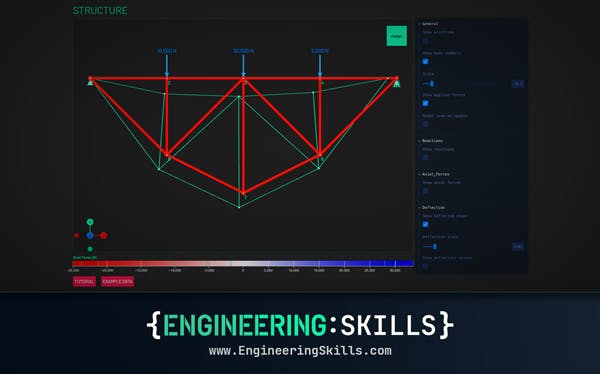
Free Truss Calculator – Quick Start Guide
An easy to use free truss calculator you can use to find member axial forces, reactions forces and deflections in 2D trusses

Dr Seán Carroll
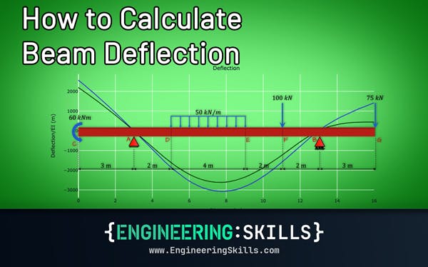
How to Calculate Beam Deflection
How to calculate beam deflection from first principles, with calculation examples
Dr Seán Carroll