Steel Beam Design - A Step-by-Step Guide using Eurocode 3
![[object Object]](/_next/image?url=%2Fimages%2Fauthors%2Fcallum_wilson.jpg&w=256&q=75)

This is the first of a series of tutorials covering the design of structural steel elements to Eurocode 3. In this first tutorial, we will focus on steel beam design.
This is a long and in-depth tutorial so it’s probably best to tackle it over the course of a couple of reading sessions!
The tutorial is broken up as follows:
✅ Section 1: A general introduction to Eurocode 3
This is a pretty light section to get us started. We set the scene by briefly reviewing and answering, What is Eurocode 3?
✅ Section 2: Steel Beam Design to Eurocode 3
In this section we further set the stage for our exploration of beam design by clarifying some terms and laying out the framework we’ll use for laying out and explaining the Eurocode 3 design process. This is the what, where, why, how, model we’ve used in previous tutorials.
✅ Section 3: Steel Beam Design Workflow
This is where we roll up our sleeves and get stuck into the design process. In this section I’ll explain each step in the design process using the framework we established in the previous section. You can think of this section as explaining the theory of beam design to Eurocode 3.
✅ Section 4: Steel Beam Design - Worked Example
No tutorial is complete without a worked example. So, in section four, we take what we learned in section 3 and deploy it in a beam design case study. If section 3 was the theory, section 4 is the practice.
✅ Section 5: Initial Sizing of Steel Beams
By this point in the tutorial, you’ll realise that designing a steel beam using Eurocode 3 is a somewhat lengthy and quite intricate process. So, in section 5 we explore ways of determining initial beam sizes.
If we start a beam evaluation (design) with the right size beam, there is less chance that we’ll work our way through the design process only to realise the beam fails to meet the design criteria.
✅ Section 6: Wrapping up and What Next
You’ve made it! In the final section, you get a pat on the back and I’ll let you know what we’re moving onto in part 2 of this series on structural steel design using Eurocode 3.
Ok, we have a lot of ground to cover…let’s get going!
1.0 General introduction to Eurocode 3
We will begin with a short introduction to Eurocode 3. It is important that we understand the basis of this document, its precursors and its jurisdiction before we proceed to use it!
What is Eurocode 3?
Eurocode 3 is the colloquial name which refers to EN 1993 Eurocode 3. The 'EN' refers to the fact that this document is a European Standard. Eurocode 3 applies to the design of buildings and other civil engineering works which use steel as the structural material.
What is included within Eurocode 3?
Eurocode 3 is split into twenty individual parts which each contain design rules which are either applicable to all steel structures or are specific to a sub-group of steel structures. For example, Eurocode 3: Design of steel structures - Part 1-1: General rules and rules for buildings (EN 1993-1-1:2005) contains general design rules whereas Eurocode 3: Design of steel structures - Part 1-5: General rules - Plated structural elements EN 1993-1-5:2006 contains rules which only relate to plated steel elements.
As a side note, each of the twenty component parts within Eurocode 3 can also have National Annexes which contain specific Nationally Determined Parameters which are only applicable to steel elements designed within a Nationalities jurisdiction. For this course, where relevant, we will refer to the United Kingdom National Annexes.
How does Eurocode 3 relate to the other Eurocodes?
Eurocode 3 should be used in conjunction with other Eurocodes as follows:
-
Eurocode 0 which contains design rules for the basis of structural design.
-
Eurocode 1 which contains design rules for the actions which are applied to structures.
-
All of the other Eurocodes when a steel element interfaces with any of the the other engineering materials (concrete, masonry, timber composite etc).
How should one use Eurocode 3?
The Eurocode 3 documents are lengthy, somewhat complex and written in a style that can make them feel intimidating to the new user. Eurocode 3 is not a textbook and was not written to give step-by-step instructions on how to design steel elements.
Rather, the document sets out the design rules which Engineers must obey for their design to be in accordance with Eurocode 3. The exact workflow through which these design rules are applied is left to the discretion and judgement of the Engineer.
In this article on steel beam design to Eurocode 3, we will establish a workflow that ensures that the design rules applicable to steel beams are captured.
2.0 Steel Beam Design to Eurocode 3
Before we jump into designing beam elements, we should first formally define a beam element. This may seem trivial but it’s important as we need to ensure that we apply the correct design rules within Eurocode 3!
So, we will say that a beam element is a structural member which transfers transverse loads across its span, to its supports, by way of bending moments and shear forces.
Eurocode 3 does not have a section called Beams; instead, it groups steel elements by the internal forces that they develop. Importantly, Eurocode 3 also considers the combination of internal forces which act simultaneously on steel elements. For example, there is an entire sub-section related to the combination of bending moment and axial force acting simultaneously on a steel element.
2.1 Defining element failure within Eurocode 3?
As is normally the case, we consider two over-arching limit states. We have the Ultimate Limit State (ULS) and the Serviceability Limit State (SLS).
The ULS case is further sub-divided into two failure mechanisms. Firstly, failure due to a lack of cross-section resistance and secondly, failure due to member buckling.
The SLS case, for the purpose of this introductory tutorial, can be thought of as referring to member deflections. Serviceability also covers checks against vibration but these are outside the scope of this article.
The following discussion assumes that you have access to a copy of Eurocode 3. We'll reference various clauses - these, unless otherwise stated, refer to Eurocode 3. Unfortunately, it's not possible to reproduce the various extracts from Eurocode 3 within this article.
If you need to purchase a copy of Eurocode 3, you can do so from the British Standards Institute (BSI). A good alternative to purchasing the complete Eurocode is to purchase Structural Eurocodes: Extracts from the Structural Eurocodes for Students of Structural Design which contains the relevant sections of Eurocode 3 as well as other Eurocodes.
Structural Eurocodes: Extracts from the Structural Eurocodes for Students of Structural Design published by the British Standards Institute.
3.0 Steel Beam Design Workflow
The following section will identify and explain the design steps which are necessary for steel beam design to Eurocode 3. The purpose of this section is to highlight what the checks are, how to conduct them and most importantly, why we are conducting these checks. In the next section we will apply all of these design checks to a worked example.
To try and structure the discussion and aid your understanding, we’ll adopt a What, Why, Where and How template:
- What - A summary of the design check.
- Where - The relevant clauses within Eurocode 3.
- Why - Why are we conducting this check?
- How - A summary of how to conduct the check.
Step 1: Determine the yield strength of steel
What?
In step 1, we need to assign a value of yield strength, , to our steel member. The value of is used extensively throughout the remainder of the design checks. The yield strength of steel varies depending on the grade chosen and also on the thickness of the component parts.
Where?
Assuming our section is formed of hot-rolled structural steel (which is a sensible assumption for most common beam sizes).
EN 1993-1-1: 2005 Table 3.1
Why?
The yield strength is the limit of elastic behaviour for the material. The yield strength is the predominant material property used in steel beam design to Eurocode 3.
How?
-
From your drawing of the steel beam, find the chosen steel grade. This will typically be S235, S275 or S355 for mild steel.
-
From the section geometry drawing, find the maximum steel thickness. This will typically be the flange thickness for a beam member.
-
Using Table 3.1, identify
Step 2: Classify the cross-section
What?
In step 2, we need to classify the geometry of the member cross-section. Eurocode 3 defines four classifications, each based on a member's ability to develop its full plastic section capacity.
-
Class 1 cross-sections are those that can form a plastic hinge with the rotation capacity required by plastic analysis without reducing the resistance.
-
Class 2 cross-sections are those that can develop their plastic moment resistance but have limited rotation capacity because of local buckling.
-
Class 3 cross-sections are those in which the stress in the extreme compression fibre of the steel member, assuming an elastic distribution of stresses, can reach the yield strength, but local buckling is liable to prevent the development of the plastic moment resistance.
-
Class 4 cross-sections are those in which local buckling will occur before the attainment of yield stress in one or more parts of the cross-section.
Where?
For the definition of the classes.
EN 1993-1-1: 2005 Clause 5.5.2
For classification of internal compression parts.
EN 1993-1-1: 2005 Table 5.2 (sheet 1 of 3)
For classification of outstand flanges.
EN 1993-1-1: 2005 Table 5.2 (sheet 2 of 3)
Why?
Classifying our cross-section is the method chosen within Eurocode 3 to simplify the analysis of different types of beam members.
As the definitions above elude to, cross-sections of class 3 and class 4 are susceptible to local buckling failure prior to yielding, whereas cross-sections of class 1 and class 2 are most likely to fail due to the lack of cross-section resistance, as opposed to local buckling.
This simple cross-section classification step allows us to predict the behaviour, and hence the relevant design checks, for a beam member based on the thickness of its constituent parts alone.
How?
-
Using the diagrams at the top of Table 5.2 (sheet 1 of 3), identify the internal compression parts. For an I-section, this will be the web of the member.
-
Calculate the value of , making sure to account for the thickness of surrounding elements and the root radius of any joints.
-
From the section geometry drawing, determine the thickness of the internal compression part(s). Again, this is typically for an I-section.
-
Now calculate the value of the quotient for the internal compression member.
-
Next, determine the value of by evaluating the quotient where is the yield strength determined in step 1.
-
We are considering a 'part' in pure bending and hence we need to use the left-most column of Table 5.2 (sheet 1 of 3).
-
Now classify the internal compression part of the section by checking if is less than 72 (Class 1), 83 (Class 2) or 124 (Class 3).
-
Repeat the process for the outstand flanges of the section. For a symmetrical I-section there is just one part to check - the flange. Which flange you might ask? Well, think about the failure of the element and what we are trying to achieve by classifying the cross-section. We want to know if the section is susceptible to a local buckling type behaviour. Which internal force causes buckling - compression! Therefore make sure you are calculating for the compression flange.
-
Once you have classified both the internal compression parts (the web) and the outstand flanges (the compression flange) then we are ready to classify the section.
-
The overall classification of the section is the lowest of the classifications of the individual parts. For example, if the internal compression part classification is class 3 and the outstand flange classification is class 1, then the section is class 3.
-
If the cross-section parts do not meet the criteria for class 3, then they are class 4. Class 4 steel members are subject to an entire Eurocode 3 document - Eurocode 3: Design of steel structures - Part 1-5: General rules - Plated structural elements. For the time being, we will assume that our section is either class 1, class 2 or class 3.
Step 3: Bending resistance
What?
In step 3, we determine the bending resistance of the cross-section. Eurocode 3 provides different design formulae for the bending resistance of members dependent on their cross-section classification (from step 2).
In general, the following should be satisfied:
where is the design bending moment acting on the member and is the design cross-sectional resistance of the member.
Note that this check is found under Clause 6.2.5. A useful observation to make is that the clauses within Eurocode 3 starting '6.2.' refer to design checks of the cross-section resistance i.e. they are not checking for member buckling. The buckling checks come later on in the design workflow and are found under clauses starting 6.3.'
Where?
EN 1993-1-1: 2005 Clause 6.2.5
Why?
We are designing a beam member which, as stated, carries load via bending moment and shear forces. In the first instance, we need to check that the design bending resistance is larger than the design bending moment.
How?
According to the cross-section classification from step 2, apply the relevant design formula to determine . For class 1 or 2 cross-sections use formula (6.13) and for class 3 cross-sections use formula (6.14).
As noted previously, don't worry about class 4 cross-sections at this point. We will look at these in much more detail in an upcoming tutorial on plate girders.
Step 4: Shear resistance
What?
Now we determine the shear resistance of the cross-section. This is a simple check which uses the shear area () for the section to calculate the shear resistance.
In general, the following should be satisfied:
where is the design shear force acting on the member and is the design cross-sectional resistance of the member.
Where?
EN 1993-1-1: 2005 Clause 6.2.6
Why?
We know that a beam transfers loads predominantly via bending moment and shear forces. In step 3, we considered the section's bending resistance, and now we need to consider the shear resistance. It’s important to recognise that a section with a high bending resistance doesn't necessarily have a high shear resistance!
How?
-
Calculate the shear area () for the section in question using the expressions in 6.2.6 (3).
-
Confirm from your structural analysis that the member is not subject to torsion.
-
If 2 is validated then proceed to calculate the plastic shear resistance using formula (6.18).
-
is the partial factor for resistance of cross-sections whatever the class is. The value can be found in 6.1 Note 2B.
Step 5: Shear buckling resistance
What?
Up to this point, we have been conducting checks based on the member's cross-section resistance. In step 5, we take a slight change of direction and now conduct a check to assess the member's web buckling resistance.
Where?
EN 1993-1-1: 2005 Clause 6.2.6 Expression (6.22)
Why?
Eurocode 3 tells us 'the shear buckling resistance for webs without intermediate stiffeners should be according to section 5 of EN 1993-1-5, if:'
We have already identified that EN 1993-1-5 is the part of Eurocode 3 which deals with plate girders. What do we know about plate girders? Well, we know that they are very deep sections, i.e. they have a very tall web.
This tall web element, if unstiffened, is susceptible to shear buckling (more on shear buckling in later tutorials!).
So, back to EN 1993-1-1, we conduct this simple check to establish whether the web of our section is susceptible to shear buckling. But wait...didn't we already say that the classification of the cross-section is the means by which susceptibility to buckling is controlled? Well, yes this is true, but the cross-section classification only considers buckling due to compression alone...which is a different behaviour to shear buckling.
However, considering all of the above, it is highly likely that if you are dealing with a standard steel section, which will likely be of class 1, 2 or 3, it will not have a web which is susceptible to shear buckling. But we still need to complete the check.
How?
This is a simple check to make.
-
Calculate which is the clear height of the web i.e. the total section height minus the flange thicknesses minus the root radii.
-
From your section geometry drawing, identify the web thickness .
-
Take the value of from step 2.
-
Use the recommended value of
-
Evaluate the inequality and ensure that the web of the section is not susceptible to shear buckling.
Step 6: Check of combined bending and shear resistance
What?
Now we jump back to cross-section resistance checks. The simplest way to understand step 6 is to take the description directly from Eurocode 3.
Where the shear force is present, allowance should be made for its effect on the moment resistance.
This is pretty clear! We need to check how the bending moment resistance (which we determined in step 3) is impacted by the presence of shear force. In practice, this check is very unlikely to govern as shear forces are rarely larger than 50% of the shear capacity (yes, there are always exceptions!).
Where?
EN 1993-1-1: 2005 Clause 6.2.8
Why?
Which area of the member in particular do we think might be impacted by the presence of shear forces?
Well, we know that the web carries the majority of the shear force in a section (think about step 4 and step 5). However, we often don't recognise that the web is also carrying a small portion of the bending moment (think about how the moment of inertia is calculated for an I-section and which elements of the cross-section contribute most). If you can picture an elastic stress distribution for a typical I-section we can see that the only place where bending stresses are NOT present is at the neutral axis.
In fact, when high shear forces are present, the web of the member is busy dealing with the shear forces and cannot 'help-out' with resisting the bending moments acting on the member as well as it might like to. In this case, we need to reduce the bending moment resistance of the member to account for this loss of resistance.
How?
-
When and when the check for shear buckling in step 5 has been satisfied, the effect of shear forces on the bending moment resistance may be neglected.
-
If 1. is not satisfied, then the reduced bending resistance of the section is calculated by allocating a reduced yield strength to the shear area of the section which contributes to the bending resistance. The following expression can be used for the reduced yield strength
Step 7: A note on additional cross-section resistance checks
In this tutorial, we’re capturing the workflow to assess a 'classic beam' member to Eurocode 3. By this, we mean that the member is subject to combined bending and shear forces only.
There are situations where a beam will need to be designed for a combination of bending, shear and axial forces and even a combination of bending, shear, torsion and axial forces. Eurocode 3 provides the for these design checks but they are less commonly used and hence not the highest priority for newcomers to Eurocode 3.
In later tutorials, we will examine the design checks required for these more complex forms of loading, but for now, we will assume that we don't need to perform any further cross-section resistance checks. The same will be true for our worked example.
Step 8: Lateral torsional buckling (LTB) resistance
What?
Earlier we talked about the two failure mechanisms which are applicable to beams. The first of these is failure due to a lack of cross-section resistance, which we covered in the previous steps. The second is failure due to buckling. In step 8, we will tackle the design checks required in Eurocode 3 to ensure that our member does not fail due to buckling.
Recall that we previously said that the classification of our cross-section into class 1/2/3/4 was the method by which we ensure that our member isn't going to fail by buckling. Well, that wasn’t the whole story!
The cross-section classification assesses the tendency of the individual components of the member to buckle locally. Recall step 2; we were checking the slenderness of the flanges and the web and comparing them against a set of Eurocode 3 criteria. Therefore, we can say that the cross-section classification is concerned with the member's local buckling.
In the proceeding steps, we are going to cover the design checks, which consider buckling of the member as a whole. You might refer to this as global member buckling.
Where?
EN 1993-1-1: 2005 Clause 6.3.2
Why?
Steel beams which have unrestrained top flanges have a tendency to fail due to lateral torsional buckling (LTB). In simple terms, LTB is to the steel beam what Euler buckling is to the steel column.
We have already conducted the design checks to show that our section has sufficient cross-sectional resistance. However, this cross-sectional resistance will never be utilised if the beam fails due to LTB before reaching the limit of its cross-sectional resistance.
The cross-sectional resistance of the member does not tell us anything about how well the member can resist buckling and therefore, we have to conduct a completely different set of design checks.
How?
The check for member buckling resistance is not a short one, and for this reason, we are going to break down the design checks into several smaller sub-sections.
8.1 Draw the bending moment diagram for the beam
This is a simple step and one that you might not have expected in a Eurocode 3 design check. However, we need to understand the distribution of bending moments in the beam in order to complete step 8.3.
8.2 Establish restraint conditions for the member
From step 8.1 we will already know the support conditions for the end of the beam. These support conditions will inform our determination of the bending moment diagram. In addition to this, we need to confirm to what degree the top flange of the beam is restrained.
We’re concerned with this because lateral torsional buckling is driven by the lateral translation of the compression flange of a steel beam, and thus, the degree to which it is restrained largely controls the tendency of the beam to fail due to LTB.
So, in general, we will say that a beam is only restrained at points where the lateral translation of the top flange is prevented.
As a side note, this is a key reason why composite (steel and concrete) beams are popular structural forms. The concrete at the top of the section fully restrains the steel beam and ensures that the entire length of the beam has full lateral restraint. This prevents the beam from failing due to LTB.
To conclude this check, let be the maximum distance between lengths of the beam which have full lateral restraint.
8.3 Calculate
is the elastic critical moment for lateral-torsional buckling.
Eurocode 3 does not provide a formula to calculate , and this is not surprising because a closed-form solution for the elastic critical moment is dependent on the geometry of the steel cross-section and several other factors.
There are many different types of steel cross-section and in order to cover all of these possibilities, Eurocode 3 would need to contain many formulae for , which simply isn't practical!
As a result, Eurocode 3 allows the Engineer the freedom to calculate as they see fit. For the purpose of this tutorial, we will assume that our beam member is doubly symmetric. An I-section is the classic example of a double symmetric section.
The closed-form expression for the elastic critical moment for a double symmetric section is as follows:
where
is the Young's modulus for steel - this is a constant,
is the shear modulus for steel - this is a constant,
is the second moment of area of the section about its weak axis - we can calculate this from first principles or obtain it from tables of values for common sections.
is the torsion constant - likewise, we can calculate this from first principles or obtain it from tables of values for common sections.
is the warping constant - we can work this out using the expression,
is the beam length between points which have lateral restraint
and are effective length factors - for the purpose of this introductory tutorial, we will assume 'fork-type' supports and that .
is the distance between the point of load application and the shear centre - is taken as positive for loads acting towards the shear centre. For a doubly symmetric section, the shear centre coincides with the centroid of the section.
and are coefficients depending on the loading and end restraint conditions - these factors are calculated empirically for the case of members subject to end-moments only, members subject to transverse loads only and members subject to combined transverse loads and end-moments. Typical values for these two coefficients can be found within industry guidance documents.
8.4 Calculate
Now that we have our value of , we need to calculate the non-dimensional slenderness, .
where
is the elastic critical moment for lateral-torsional buckling from step 8.3.
is the yield strength for the steel, which we determined in step 2.
is the appropriate section modulus as follows:
- for Class 1 or 2 cross-sections.
- for Class 3 cross-sections.
- for Class 4 cross-sections.
EN 1993-1-1: 2005 Clause 6.3.2.2
8.5 Select the buckling curve and find
Now we use Table 6.4 to determine the correct buckling curve. These buckling curves allow us to determine the imperfection factor which we must account for during our lateral torsional buckling check.
Once we know the correct buckling curve, we use Table 6.3 to determine .
EN 1993-1-1: 2005 Table 6.3 and Table 6.4
8.6 Calculate the reduction factor
Now we are at the point where we can calculate the reduction factor . All of the sub-steps we have completed in step 8 have been leading us towards calculating this reduction factor.
First, we calculate as follows:
And using we can now calculate as follows:
EN 1993-1-1: 2005 Clause 6.3.2.2
8.7 Calculate the buckling resistance for the beam
We have now calculated our reduction factor which leaves us to just determine the reduced bending moment resistance for the member.
where is taken to be in accordance with 6.1 NOTE 2B
EN 1993-1-1: 2005 Clause 6.3.2.1
Step 9: Serviceability check
What?
So far, all of the design checks we have completed have been at ULS. We must not overlook the SLS design checks as these can often govern member design in practice. For example, a steel beam spanning between two columns may well have sufficient capacity at ULS but it may deflect to the extent that it does not function in service.
Where?
EN 1990 – Annex A1.4
Why?
We complete these design checks to ensure that the steel member functions when under service conditions.
How?
We need to determine the maximum deflection in the beam member. Typically, we are considering deflection in the vertical axis but there are situations when horizontal deflection is relevant.
Closed-form expressions for deflection are readily available for statically determinate beams with simple loading arrangements. For more complex support conditions and loading arrangements, a computerised solver is likely to be the fastest way to determine in-service deflections. You can use a commercial programme, or build your own and learn how it works along the way!
Beam and Frame Analysis using the Direct Stiffness Method in Python
Build a sophisticated structural analysis software tool that models beams and frames using Python.
After completing this course...
- You’ll understand how to model beam elements that resist axial force, shear forces and bending moments within the Direct Stiffness Method.
- You’ll have your own analysis software that can generate shear force diagrams, bending moment diagrams, deflected shapes and more.
- You’ll understand how to model rotational pins within your structures, inter-nodal distributed loading and realistic flexible supports.
All that follows is to compare the predicted deflection against a set of recommended limits for different design situations.
- Cantilevers, = span/180
- Beams carrying brittle finishes, = span/360
- Other beams, = span/200
4.0 Steel Beam Design - Worked Example
By far, the best way to understand Eurocode 3 is to work through a design example. In this section, we’ll go through each of the design checks we completed in section 3 of this tutorial step-by-step.
To get the most from this section, have your copy of Eurocode 3 available so that you can follow each of the design checks - or better yet…try working through the problem yourself first!
4.1 Setting up the problem
Steel beams are typically arranged as a lattice of connected members. The primary steel beams span between columns, which act as vertical supports, whilst the secondary steel beams span between primary steel beams. Obviously, the primary steel beams provide vertical support to the secondary steel beams.
An important feature of this typical arrangement of beams is that the secondary beams can provide lateral restraint to the primary steel beams at the connection points. As we have discussed, the length between points of lateral restraint is a key factor when determining the buckling resistance of a member.
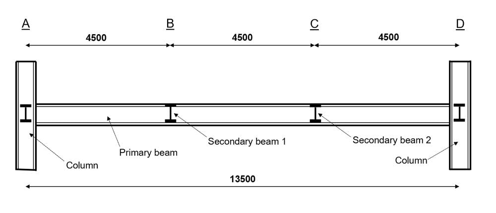
Fig 1. General arrangement of worked example beam.
4.2 Loading
Let’s start by stating the beam loading and the load cases we’ll be considering.
4.2.1 Permanent Actions ()
Self-weight, Concentrated Load at Point B (vertical reaction for beam S1) = Concentrated Load at Point C (vertical reaction for beam S2) =
4.2.2 Variable Actions ()
Concentrated Load at Point B (vertical reaction for beam S1) = Concentrated Load at Point C (vertical reaction for beam S2) =
4.3 Load Cases
4.3.1 Partial factors for actions
Partial factor for permanent actions, Partial factor for variable actions,
4.3.2 Combination
A useful rule of thumb to follow for choosing a load case is that EN 1990 expression 6.10b will normally be the governing case unless the permanent actions are greater than 4.5 times the variable actions.
On this basis, we’ll consider the following combination at ULS:
where:
'sup' defines an unfavourable action i.e. an action which causes forces which are unfavourable to the member.
'inf' defines a favourable action.
For this example, the expression simplifies down to:
Because…
-
We don't have any favourable permanent actions, so .
-
Our variable actions are not independent of each other and therefore there can be no accompanying actions, which makes .
4.4 Analysis
Now, we progress to the structural analysis stage, which will allow us to determine the internal forces (against which we will conduct our member design checks).
Typically, for the sale of time, I recommend that you make use of a numerical beam solver to conduct the analysis. For a statically indeterminate beam, you may want to check out the solver mentioned above but for a simply supported beam like this, you can either do the calculations by hand or use the simple beam solver that we build in this free Python Project.
4.4.1 Applied loads
UDL (self-weight):
Concentrated Load at B:
Concentrated Load at C:
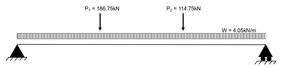
Fig 2. Analysis general arrangement.
4.4.2 Bending moments
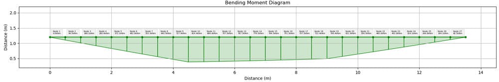
Fig 3. Bending moment diagram calculated using this beam and frame solver.
4.4.3 Shear Forces
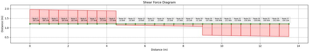
Fig 4. Shear force diagram calculated using this beam and frame solver.
4.5 Initial section choice
As you develop more experience of designing steel beams to Eurocode 3, you will begin to make initial size estimates for steel beams more and more accurately. To fast-track this process, the final section of this tutorial contains some useful recommendations and rules of thumb for choosing the initial size of steel beams.
For this worked example, we will try an S355 686x254x140 UB.
From the section properties tables, we can extract the relevant section information as follows:
- Depth, mm
- Width, mm
- Web thickness, mm
- Flange thickness, mm
- Root radius, mm
- Depth between fillets, mm
- Second moment of area about y-y axis, cm
- Second moment of area about z-z axis, cm
- Warping constant, dm
- Radius of gyration about y-y axis, cm
- Radius of gyration about z-z axis, cm
- Plastic modulus y-y axis, cm
- Plastic modulus z-z axis, cm
- Elastic modulus y-y axis, cm
- Elastic modulus z-z axis, cm
- Area, cm
- Modulus of elasticity, N/mm
- Shear Modulus, N/mm
Note: the units for each of the above properties are those which are typically used in industry. You will find that using these units is more convenient and avoids using extremely large or small numbers!
4.6 Cross-section classification
Step 1: Determine the yield strength of the steel,
- Our section is S355 steel
- We have mm mm
N/mm
EN 1993-1-1: 2005 Table 3.1
Step 2a: Classify the cross-section - Outstand of compression flange
The limiting value for a Class 1 section is .
Evaluating the limiting value:
The flange in compression is Class 1
EN 1993-1-1: 2005 Table 5.2 (sheet 2 of 3)
Step 2b: Classify the cross-section - Web
The limiting value for a Class 1 section is .
Evaluating the limiting value:
The section of web in compression is Class 1
EN 1993-1-1: 2005 Table 5.2 (sheet 1 of 3)
Step 2c: Overall classification
Both the flange and the web in compression are Class 1. Therefore the overall section classification is Class 1.
4.7 ULS Checks - Cross-section resistance
Step 3: Bending resistance
We are only concerned with bending about the beam’s major axis as there are no transverse loads applied to the beam. If we needed to consider bi-axial bending then it would be necessary to introduce additional subscripts to distinguish between the two principal axes of bending.
In this worked example, we need to validate the following expression:
EN 1993-1-1: 2005 Clause 6.2.5 (Exp. 6.12)
We have a Class 1 section and therefore, the following applies:
EN 1993-1-1: 2005 Clause 6.2.5 (Exp. 6.13)
The bending moment resistance of the proposed section is adequate.
Step 4: Shear resistance
We need to validate the following expression for the axis:
EN 1993-1-1: 2005 Clause 6.2.6 (Exp. 6.17)
We have already established that the section is Class 1. A Class 1 section is able to develop its full plastic moment of resistance and therefore we can consider the full plastic shear resistance for the section. Furthermore, there is no design torsion acting on the member. This leads to the following expression:
where is the shear area.
EN 1993-1-1: 2005 Clause 6.2.6 (Exp. 6.18)
We are considering a rolled I section and so for load parallel to the web (i.e. along the -axis:
where,
and
therefore,
EN 1993-1-1: 2005 Clause 6.2.6 (3)
Calculating ,
and evaluating its acceptability,
The shear force resistance of the proposed section is adequate.
Step 5: Shear buckling resistance
We need to validate the following to ensure that shear buckling resistance is adequate:
EN 1993-1-1: 2005 Clause 6.2.6 (Exp. 6.22)
We have all of the following values so this check is rather simple,
EN 1993-1-1: 2005 Clause 6.2.6 (6)
Therefore, the section is not susceptible to shear buckling and we do not need to conduct additional checks for this mode of failure.
Step 6: Combined bending and shear resistance
We need to validate the following:
kN
We have shown that and there is no requirement to reduce the bending resistance due to the presence of the shear force.
EN 1993-1-1: 2005 Clause 6.2.8
Step 7a: Check for Torsion
We need to validate the following:
For our worked example, and so this check is not critical.
EN 1993-1-1: 2005 Clause 6.2.7
Step 7b: Combined bending, shear and axial force
In this worked example, we assume that there is no axial force present in the beam and therefore the design check for combined bending, shear and axial force is not critical.
EN 1993-1-1: 2005 Clause 6.2.10
4.8 ULS Checks - Buckling Resistance
Step 8.1: establish restraint conditions for the member
The connection of the secondary beams to the primary beams represents a point of restraint. The end supports of the beam i.e. at the columns, also represent points of restraint.
This means that the beam member is split into three un-restrained lengths:
m.
Step 8.2: draw the bending moment diagram and establish values for and
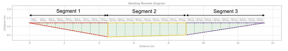
Fig 5. Splitting the beam into critical length segments.
Let us start with :
For segment 1 (left-hand side):
kN.m kN.m
For segment 2 (middle):
kN.m kN.m
= 1.073
For segment 3 (right):
kN.m kN.m
Now we move onto :
When the bending moment diagram is linear along a segment i.e. between two points of lateral restraint, . For our worked example, the bending moment diagram is linear across each of the three segments.
Step 8.3 Calculate
is the elastic critical moment for lateral-torsional buckling. We have three critical but equal, length values, , and . Whilst these values are equal, they will have unique corresponding values for since the bending moment distribution in each segment is different.
Before we start, we can make a quick simplification to the formula for . Since = 0 and we are making the assumption that i.e. fork type supports.
Therefore:
Step 8.4 Calculate
Now we calculate the non-dimensional slenderness, .
EN 1993-1-1: 2005 Clause 6.3.2.2 (1)
Step 8.5 Select the buckling curve and find
Next, we use Table 6.4 to determine the correct buckling curve. These buckling curves allow us to determine the imperfection factor which we must account for during our lateral torsional buckling check.
We are considering a hot-rolled I-section with and therefore, we choose buckling curve .
Once we know the correct buckling curve, we use Table 6.3 to determine .
EN 1993-1-1: 2005 Table 6.3 and 6.4
Step 8.6 Calculate the reduction factor
Now we’re at the point where we calculate the reduction factor . All of the sub-steps we have completed in step 8 have been bringing us to this point and calculating the reduction factor.
First we calculate as follows:
And using we can now calculate as follows:
EN 1993-1-1: 2005 Clause 6.3.2.2 Expression 6.56
Step 8.7 Calculate the buckling resistance for the beam
We have now calculated our critical buckling reduction factor which leaves us to finally determine the reduced bending moment resistance for the member.
where is taken to be in accordance with 6.1 NOTE 2B
Therefore,
i.e. the buckling resistance of the section is adequate.
EN 1993-1-1: 2005 Clause 6.3.2.1 Expression 6.54
4.8 SLS Checks
Now we need to ensure the beam satisfies the serviceability limit state by ensuring that the predicted service deflections are within allowable limits. I’ve calculated the maximum service deflection to be .
You can use software to do this or simply use published deflection equations and the principle of superposition to determine the deflection from each load.
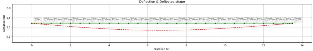
Fig 6. Deflection at SLS, .
For a typical steel beam which may be required to support brittle finishes i.e. plasterboard, glazing or masonry cladding, the limiting deflection is span/360.
Therefore mm
Since we can accept the predicted deflection and consider the beam to have satisfied the serviceability limit state.
This, in fact, wraps up our worked example. We have successfully confirmed the suitability of our candidate beam. It has been shown to be adequately strong (ULS) and stiff (SLS) to withstand the applied loading, according to the guidance in Eurocode 3.
This still leaves the question of how should be identify a suitable candidate beam size? As we’ve seen, there is a lot of work involved in a detailed beam design - so we’d like to do everything we can to ensure that the beam we start out designing, is likely to pass all of our checks. This is where initial sizing guides and rules of thumb come in very handy. We’ll discuss some of these next.
5.0 Initial Sizing of Steel Beams
As engineers, we often need to make initial estimates for the sizes of structural elements. This might be required to allow an architect to incorporate the structural depth into their space planning of a structure or alternatively to provide an initial input of member size to a 3D FEM model.
Making an initial estimate for a steel beam is not so simple! What makes this a challenge?
-
We have to make an assumption on the grade of steel and the maximum thickness of the component parts.
-
We might know the span of the beam but we won't necessarily know the top flange restraint conditions. As we have discussed, the top flange restraint is a crucial factor in determining the buckling resistance of a steel beam.
-
We can probably estimate the bending moment diagram but we might not know this exactly.
-
As we’ve seen from the worked example, calculating the reduction factor is not a quick process!
Considering the above factors, we have a couple of different techniques at our disposal which we can use for initial beam sizing:
Method 1: Industry span-to-depth ratios
The existing steel structures around the world can provide data on member size. In particular, if we examine the span of a steel beam compared to its depth we can gain a set of 'rules of thumb' for different steel beam applications.
For the purpose of initial sizing of typical steel beams, the following can be used:
- Primary beams i.e. beams spanning column to column:
For example, when a primary beam spans 8000mm, a suitable initial section depth () might be between 533mm and 615mm.
- Secondary beams i.e. beams spanning between primary beams:
For example when a secondary beam spans 6000mm, a suitable initial section depth () would be between 300mm and 333mm.
These span-to-depth ratios are very simple and somewhat crude but can be useful for a quick estimate of beam depth.
Method 2: Shortcut to
Recall step 8.3, where we determined in order to determine . Calculating is rather time-consuming, and in a first approximation, it would be good to be able to avoid this lengthy calculation step.
Luckily, if we limit our choice of section to doubly symmetric sections (I or H) then we can use a neat shortcut to determine .
Our new expression for is as follows:
where
and
So, how do we use this formula?
Step 1: Estimate the value for
In most engineering arrangements, the bending moment distribution can be estimated. Using this, we assume a value for . If in doubt, assume that .
Step 2: Determine
Strictly, is from the previous steel design code, BS5950-1:2000, but since we are only using it for initial member sizing, then we are OK to use this older design code.
is the quotient of the design modulus of the section and the plastic modulus of the section (about the axis of bending in question).
For a class 1 or 2 section, . For initial sizing, it is useful to assume a class 1 or 2 section.
Step 3: Set
According to Eurocode 3, lateral torsional buckling effects can be ignored if . So you might be asking why we don't just set . Well, if we did this, then we would require huge steel sections for simple applications!
Instead, it is more sensible to set to an intermediate value, let's say 1 (although this doesn't really matter as we will iterate in the next steps!).
Step 4: Rearrange for
We now have all of the values in our expression except . So, the next step is to re-arrange for this single unknown.
Step 5: Choose a suitable section (using )
Now, all that remains is to select a steel section which has a value of that is at least equal to the value calculated in step 4! There are plenty of tabulated steel section tables available online which have the values for common steel sections listed.
Step 6: Jump directly to determining
Now we have a value for , we can now repeat steps 8.5, 8.6 and 8.7 from the worked example. As a reminder, these were:
-
Select the buckling curve and find as per EN 1993-1-1: 2005 Table 6.3 and 6.4
-
Calculate as per EN 1993-1-1: 2005 Clause 6.3.2.2 Expression 6.56
-
Calculate as per EN 1993-1-1: 2005 Clause 6.3.2.2 Expression 6.56
Step 7: Now calculate
All that remains is to determine the bending moment resistance of the section. This is exactly what we did in step 8.7 of the worked example.
Once this check is complete, if you find that the bending moment resistance of the section is less than the design bending moment, then return to step 3, adjust your target value for and then repeat steps 5-7.
6.0 Wrapping up and What Next
I hope you've found this tutorial on the design of steel beams to Eurocode 3 helpful. The aim of this tutorial is to give you the skills and confidence to use Eurocode 3 Part 1-1 to design steel beams. You should now have a good understanding of the different design checks which we conduct and the reason why we conduct them.
In the next tutorial in this steel design series, we focus our attention on the design of steel columns to Eurocode 3.
How do steel columns differ to steel beams? Are there any similarities between these two member types? When does a steel column become a steel beam?
We will answer all of these questions, and quite a few more, in the next article, so keep your eye out for it!
Featured Tutorials and Guides
If you found this tutorial helpful, you might enjoy some of these other tutorials.

Steel Truss Design to Eurocode 3
Learn how to design one of the most common structural forms - the steel truss

Callum Wilson

A Pynite Crash Course - Open Source Finite Element Modelling for Structural Engineers
Part 1 - Get hands-on with V1.0 of this exciting new Python FEA library

Dan Ki

Steel Column Design using Eurocode 3 - A Complete Guide
Learn how to design steel columns subject to compression and biaxial bending.
Callum Wilson