Free Truss and Beam Calculator - A Structure Bench Quick Start Guide

You can build and solve a model straight away, with no account and nothing to install. Open the 2D editor or the 3D editor in a new tab and follow along as you read.
You can also check out the Learn page on Structure Bench. It hosts two really helpful types of resources:
- Learning Pathways are guided tutorials that walk you through how to use various Structure Bench features and teach a little engineering along the way,
- Video tutorials where I walk through how to use Structure Bench, and you essentially watch over my shoulder.
Here's are two good starter videos, one for 2D modelling and one for 3D modelling...
1.0 What is Structure Bench?
Structure Bench is the browser-based structural analysis platform from EngineeringSkills. It’s a suite of structural analysis tools that I’ve been building in the background as a complement to the courses here on EngineeringSkills.
The original idea was to provide users with an easy-to-access structural analysis solver in their browser, tightly integrated with course lectures. The original plan was to focus on truss and moment frame analysis. Just a simple tool that would allow you to build and solve small models in 2D.
It was meant to be an aid while working through course lectures - in fact, the original idea came while developing the The Structural Behaviour Course. But it has grown in capability way beyond what I first envisaged. So much so that it now lives under its own banner at StructureBench.com.
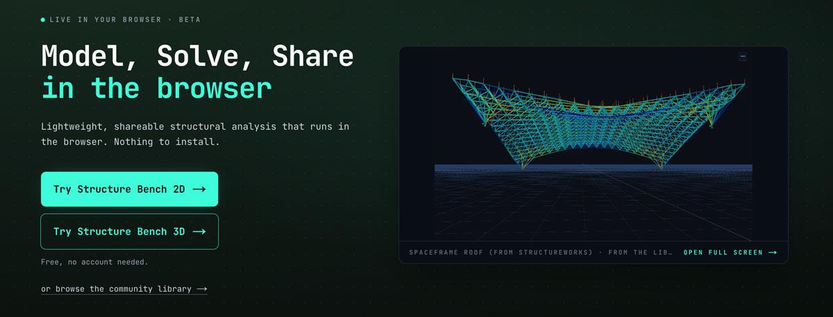
Fig 1. The Structure Bench home page, with links to the free 2D and 3D editors.
Structure Bench has its own learning resources that are aimed at getting new users comfortable with the platform. You can find those here. There are multi-step learning pathways dedicated to specific features, as well as video walkthroughs where you look over my shoulder as I demo various features.
In this quick guide, we'll work through five very simple structures, all of which are in the Structure Bench public model library, so you can open each one and explore it yourself. We'll start with a 2D Pratt truss, then a simply supported beam, a continuous beamand finish with a 3D space truss and a braced building frame. By the end of this guide, you'll have a good idea of how to build and solve your own structures.
Again, these structures are very simple and really serve as a way of introducing the tools. For a more complete introduction to modelling and analysis, consider working through the free learning pathways - they’ve been built specifically to familiarise new users with the modelling and analysis Structure Bench:
The 2D and 3D general-purpose solvers are free to use with generous model size limits. You don’t even need an account. If you want to save your models, you need a free EngineeringSkills account (get one here). If you want to unlock the full capability of Structure Bench, you’ll need an EngineeringSkills membership. This gives you access to all EngineeringSkills courses and tutorials in addition to unlimited access to Structure Bench and all of its features.
All Access Membership
Learn, revise or refresh your knowledge and master engineering analysis and design

Access Every Course and Tool
- Unlimited access to Structure Bench - online analysis platform
- Over 1178 lectures & over 244 hours of HD video content
- Access member-only 'deep dive' tutorials
- Access all downloads, pdf guides & Python codes
- Access to the StructureWorks Blender addon
- Packed development roadmap of courses & tutorials
- Price Guarantee – avoid future price rises as we grow
- Priority Q&A support
- Course completion certificates
- Early access to new courses
When it comes to modelling, Structure Bench follows the same norms you're familiar with from other structural analysis tools. You build a model from nodes, members, supports and loads. Pressing solve will return reaction forces, the internal actions in every member, and the displacements of every node. Structure Bench draws the results as diagrams on the model and also lists them in tables, so you can read any value you need.
One thing to be aware of is that Structure Bench isn't designed for a phone or tablet screen. So you'll want a laptop or desktop with a mouse for modelling.
1.1 What's free and what needs a membership
Anyone can build and solve a 2D or 3D model in Structure Bench for free. If you're not signed in, you can use the 2D and 3D trial editors straight away, but your model isn't saved when you leave the page. If you sign in with a free EngineeringSkills account, you can also save your models and projects and come back to them later.
Free models are limited in size. In 2D, a free model can have up to 60 nodes and 120 members. An EngineeringSkills membership removes the size limit and opens the more advanced features of Structure Bench, which we'll look at in section 7.
The free editor is the same editor members use, Fig 2. The Build tab on the left contains the materials, sections, load cases and load combinations. The toolbar along the top has the tools for placing nodes, members, supports and loads, and the canvas on the right shows the model.
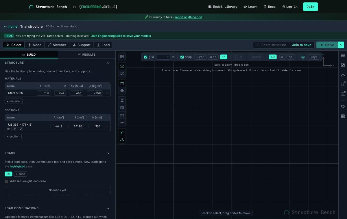
Fig 2. The 2D editor, before we've added anything. The Build tab (left) and the canvas (right).
2.0 Using the free truss calculator
Let's start with a truss. We'll analyse a Pratt truss, which is a common form for roof trusses and short-span bridges. If you'd like to open the finished model and follow along, you'll find it in the public model library here.
2.1 The model
Our truss is 24 m long and 3 m deep, and it has eight bays (or panels) of 3 m each. It consists of nine top chord nodes, nine bottom chord nodes and 33 members. The top and bottom chords are CHS 168.3 x 8.0 sections and the verticals and diagonals are CHS 88.9 x 5.0 sections, all in S355 steel. The diagonals slope down towards midspan. This is what defines a Pratt truss, and under gravity loading it puts the diagonals in tension.
The truss is supported by a pin at the left end and a roller at the right end. A 20 kN load acts downwards at each internal top chord node, and a 10 kN load acts at each of the two end nodes, so the total load is 160 kN.
To build a model like this yourself, you’d place the nodes with the Node tool (or type their coordinates into the Nodes table) and connect them with the Member tool. Each member has a type: a frame member resists bending, shear and axial force, while a truss member is pinned at both ends and carries axial force only. Everything in this model is a truss member. Finally, add the supports with the Support and point loads with the respective tools and press Solve.
To be honest, within about 2 minutes of poking around the interface, you'll have worked out how to build simple models like this. And remember, there's plenty of walkthrough videos where I build models just like this in real time if you get confused.
2.2 Reading the axial forces
With the model solved, switch on the Axial force layer, Fig 3. Members in compression are drawn in red and members in tension are drawn in blue, and the thickness of each member indicates the size of its axial force. Value labels print the force on each member.
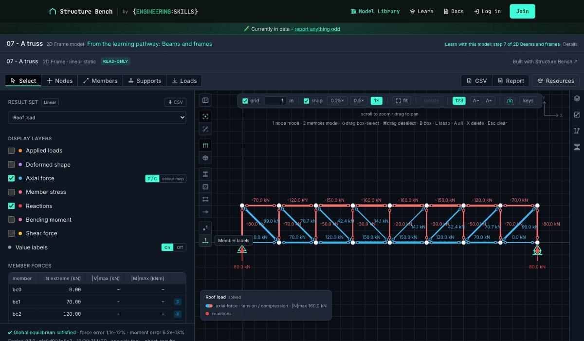
Fig 3. The axial forces in our Pratt truss. Compression is red, tension is blue, and the thickness shows the magnitude.
You'll notice that the top chord is in compression and the bottom chord is in tension. Both chord forces grow from the supports towards midspan, where the top chord carries 160.0 kN of compression and the bottom chord carries 150.0 kN of tension. The diagonals are all in tension and the verticals are all in compression. The reactions are 80.0 kN at each end, which is half the total load, as we'd expect from symmetry.
In some ways, we can think of a simply supported truss as a beam with its internal workings on show. A simply supported beam's bending moment grows from zero at the supports to a maximum at midspan. In the truss, this moment is resisted by the couple formed by the top and bottom chord forces, with a lever arm of 3 m. Similarly, the shear in a beam is greatest near the supports, and in the truss the diagonal forces are greatest near the supports too.
2.3 Checking the results by hand
Now let's check two of these forces by hand. If you need a refresher on the methods we'll use, take a look at this EngineeringSkills tutorial, Truss Analysis using the Method of Joints and Method of Sections.
We'll use the method of sections to determine the force in the bottom chord at midspan. We can cut the truss through panel 4, between 9 m and 12 m, and look at the sub-structure to the left of the cut. The cut passes through three members, the top chord, the diagonal and the bottom chord. If we take moments about the top node at 9 m, where the top chord and the diagonal meet, only the bottom chord force is left in the equation. The bottom chord force multiplied by the 3 m depth balances the moment of the reaction and the loads to the left of the cut, so we have,
This is a tension force, and it matches the 150.0 kN that Structure Bench returns.
We'll use the method of joints at the first top node to calculate the force in the end diagonal.** . The end vertical carries the 80 kN reaction up to this node, and the 10 kN load acts down on it, which leaves 70 kN that must be balanced. The only other member at this joint with a vertical component is the end diagonal, which is inclined at 45°, so its force is,
of tension. Structure Bench reports 99.0 kN.
2.4 The deflected shape
Next, switch off the axial forces and look at the Deformed shape layer, Fig 4. The deflections are small compared with the 24 m span, so the slider beside the layer exaggerates them to make the shape visible. The largest displacement is labelled on the model, 15.3 mm, at the midspan top node. The Displacements table also lists the displacement of every node.
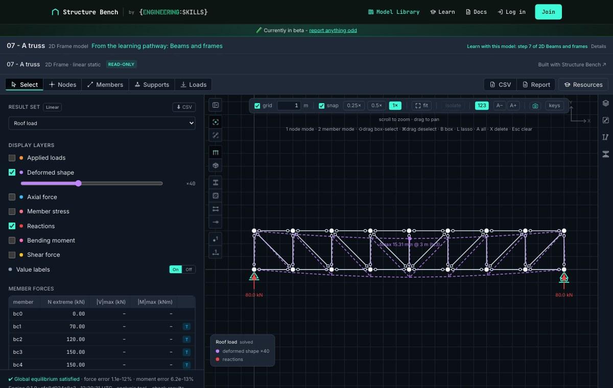
Fig 4. The deflected shape of the truss, exaggerated 40 times. The member forces table is on the left.
Notice that every member stays straight - this is a subtle but important observation. Each truss member only carries axial force, so it can only get longer (in tension) or shorter (in compression). The overall deflection of the truss is the result of all of these small changes in length. When we zoom out, though, we see the familiar deflected shape of a simply supported beam.
Structure Bench does the stiffness method for you, but it's well worth understanding what happens when you press Solve. In this course, I walk you through the theory of the direct stiffness method and how to build your own 2D truss analysis code in Python.
The Direct Stiffness Method for Truss Analysis with Python
Build your own finite element truss analysis software using Python and tackle large scale structures.
After completing this course...
- You’ll understand how to use the Direct Stiffness Method to build complete structural models that can be solved using Python.
- You’ll have your own analysis programme to identify displacements, reactions and internal member forces for any truss.
- You’ll understand how common models of elastic behaviour such as plane stress and plane strain apply to real-world structures.
3.0 Using the free beam calculator
Now let's use Structure Bench as a free beam calculator. We'll start with a simply supported beam, where we can check the results with simple statics, and then we'll look at a statically indeterminate continuous beam.
3.1 A simply supported beam
Our beam spans 6 m between a pin and a roller and carries a uniformly distributed load of 20 kN/m along its full length. It's a UB 305 x 165 x 40 in S355 steel, picked from the section catalogue, which gives it a second moment of area of 8,500 cm⁴. The model can be found in the here in the public library.
The model consists of two nodes and one frame member. It's built much the same way as the previous truss model - except with a frame rather than a truss member. When it's solved, switch on the Bending moment and Shear force layers, Fig 5. The bending moment is the parabola drawn on the tension side of the beam, which is the underside here, and its peak is labelled 90.0 kNm at 3 m. The shear force diagram is a straight line from 60.0 kN at the left support, through zero at midspan, to -60.0 kN at the right support.
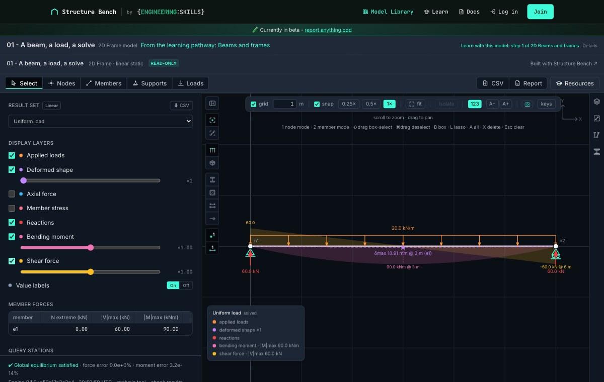
Fig 5. The shear force and bending moment diagrams for the simply supported beam.
Each of these numbers agrees with the standard formulas. The reactions and the shear at the supports are kN, and the midspan moment is kNm. The deflection is worth checking too. With GPa and , the midspan deflection of a simply supported beam under a uniformly distributed load is,
and Structure Bench labels the maximum deflection as 18.91 mm at 3 m. If you'd like a refresher on how the diagrams and the deflection are worked out by hand, take a look at the EngineeringSkills tutorials on shear and moment diagrams and beam deflection.
3.2 Reading values anywhere along a member
The diagrams give us the overall picture, but very often we need a value at a particular point. With Select active in the toolbar, hover over a member and a probe card shows the axial force , the shear force , the bending moment and the deflection at the cursor, Fig 6. At midspan, it shows , kNm and mm. As you move the cursor towards a support, the shear grows and the moment falls to zero. Click to pin a probe card in place, and click the pinned card to remove it.
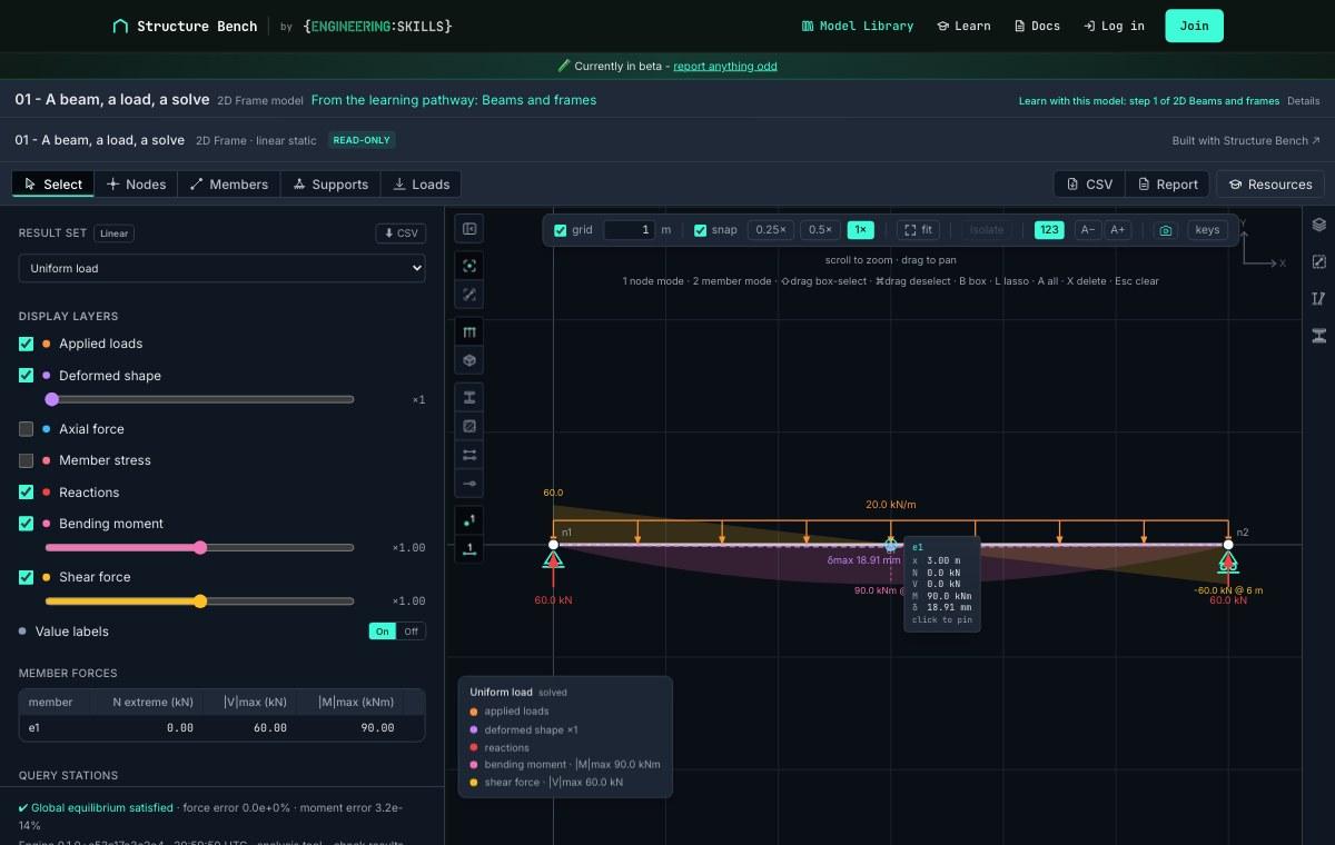
Fig 6. The probe card at midspan shows the internal forces and the deflection at the cursor.
3.3 A continuous beam
A beam that runs over one or more internal supports is referred to as a continuous beam. Our example is two 6 m spans of a UB 356 x 171 x 51 over a middle support, with 20 kN/m on both spans, Fig 7. You'll find it in the library here.
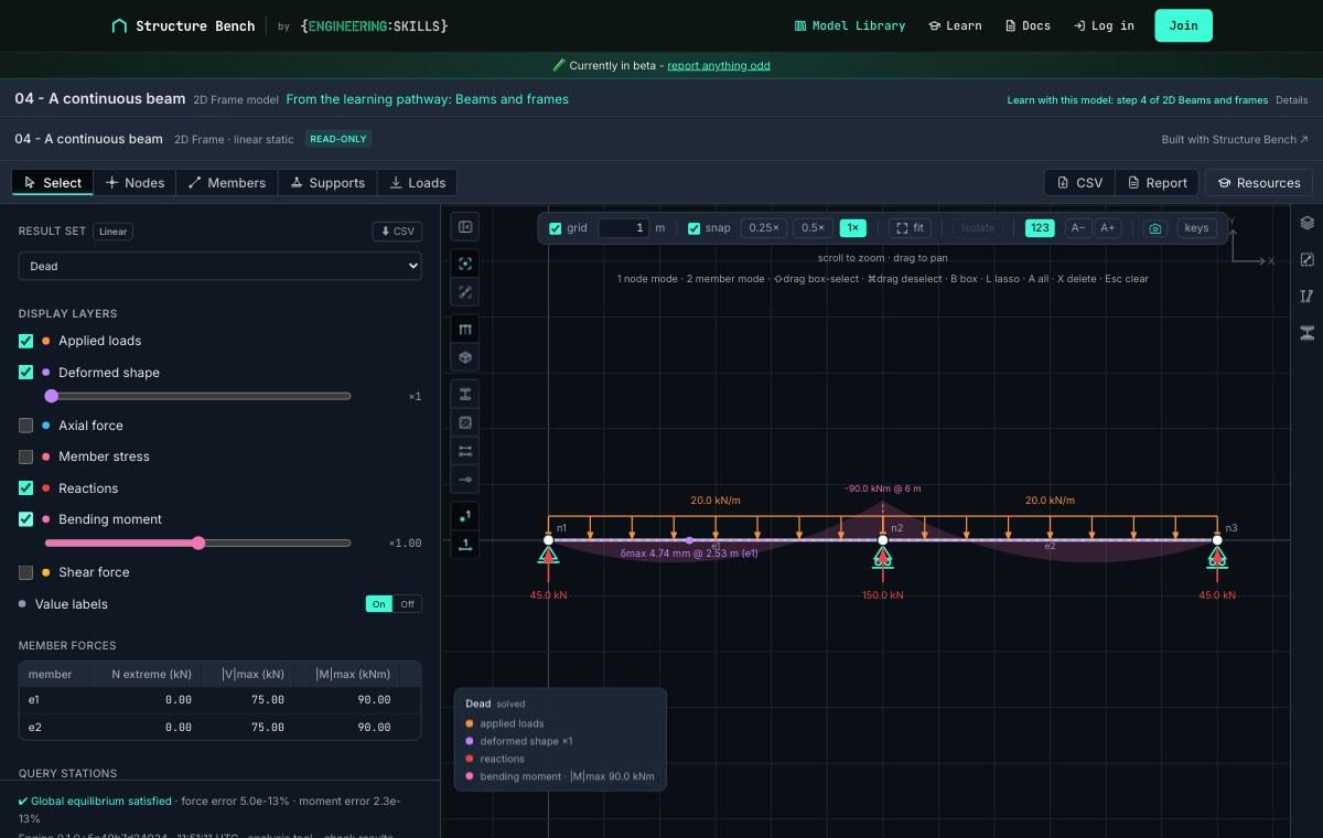
Fig 7. The bending moment diagram for the two-span continuous beam, with the hogging moment over the middle support.
The bending moment diagram looks quite different from the simply supported case. Over the middle support, the beam develops a hogging moment of -90.0 kNm, with tension in the top of the beam. In each span, the sagging moment peaks at 50.6 kNm, and this peak isn't at midspan. It occurs 2.25 m from each end support. The reactions are 45.0 kN at each end and 150.0 kN at the middle support. This is quite different from the 60 kN, 120 kN and 60 kN that two separate simply supported spans would give.
We can check all of these numbers with the standard results for two equal spans under a uniformly distributed load. The support moment is kNm. The end reactions are kN, so the middle support carries the rest of the 240 kN total load, kN. The peak sagging moment is kNm, and it occurs at m from the end support, where the shear force passes through zero.
Don't confuse a beam that spans continuously over an internal support (what we have here) with two beams that are hinged at the internal support. They behave very differently. If you add a hinge over the middle support in Structure Bench and solve again, the hogging moment disappears and each span behaves as a simply supported beam.
If you'd like to understand how a frame solver like this works, this course walks you through the direct stiffness method for beams and frames, and builds a complete analysis code in Python. After completing the truss course mentioned above and this beam and frame course, you will have an excellent understanding of 2D matrix-based structural analysis.
Beam and Frame Analysis using the Direct Stiffness Method in Python
Build a sophisticated structural analysis software tool that models beams and frames using Python.
After completing this course...
- You’ll understand how to model beam elements that resist axial force, shear forces and bending moments within the Direct Stiffness Method.
- You’ll have your own analysis software that can generate shear force diagrams, bending moment diagrams, deflected shapes and more.
- You’ll understand how to model rotational pins within your structures, inter-nodal distributed loading and realistic flexible supports.
4.0 Going 3D
Everything we've done in the editor so far works the same way in three dimensions. The free 3D editor has the same toolbar, the same layers and the same tables, and you can orbit around the model by dragging on the canvas. Each 3D frame member can bend about both of its axes, twist (about its longitudinal axis), and carry axial force.
4.1 A space truss
Our first 3D structure is a square pyramid of four CHS 88.9 x 5.0 truss members. The feet are pinned at the corners of a 3 m square, the apex is 2.5 m above them, and a 100 kN load acts downwards at the apex, Fig 8. Open the model from the library here.
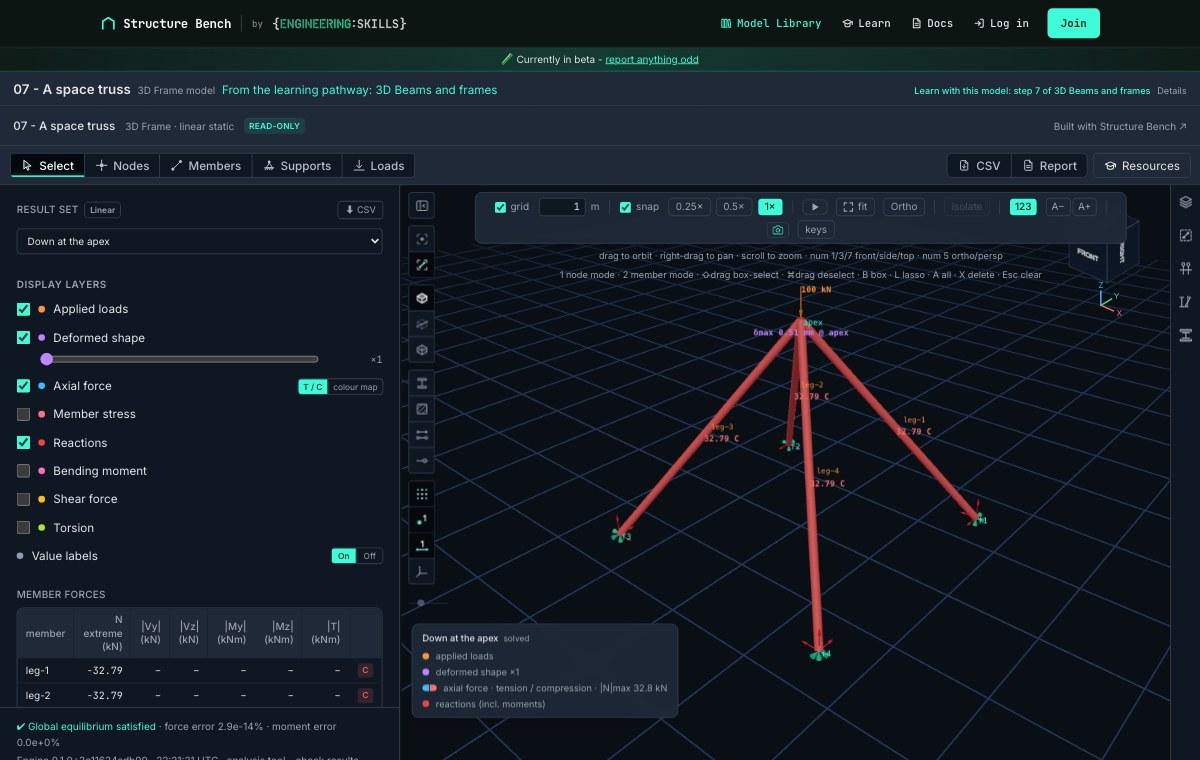
Fig 8. A square pyramid space truss under a vertical load at the apex. Each leg carries 32.79 kN of compression.
Each leg carries 32.79 kN of compression. We can check this by the method of joints at the apex. Each leg runs 2.121 m horizontally (half the diagonal of the 3 m square) and 2.5 m vertically, so it has a length of 3.279 m. The angle between each leg and the vertical therefore has . By symmetry, the four legs share the 100 kN load equally, and only the vertical component of each leg force resists it, so,
of compression in each leg. Each foot then provides a vertical reaction of 25 kN.
If you want to go deeper into how a 3D truss is analysed, I cover this in detail in the EngineeringSkills course 3D Truss Analysis using the Direct Stiffness Method. It may seem like I have a course to pitch you in every section...I guess I do! But remember, this is just because the courses came first and Structure Bench only came into existence initially as a way of helping people working through my courses. My primary goal is not to provide a black box analysis tool - it's to help you understand what's happening inside the black box through my EngineeringSkills courses :)
4.2 A braced building frame
Finally, let's look at something closer to a real building. This model is a two-storey frame, two bays by two bays on plan, braced in both directions. It's analysed under dead load and under wind from the X and Y directions, and the load combinations are built from these cases, Fig 9.
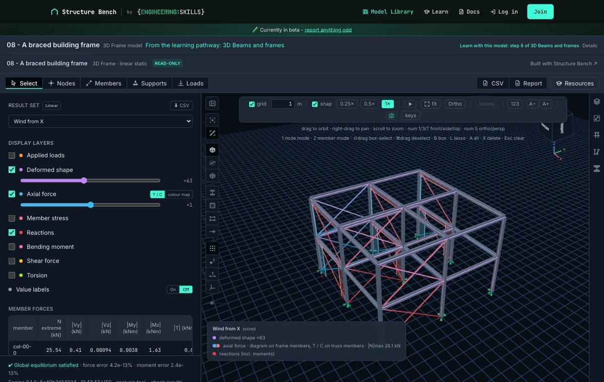
Fig 9. A two-storey braced building frame under wind from the X direction. The braces in tension are blue and those in compression are red.
Under wind from the X direction, the bracing in the three frame lines parallel to X provides the lateral load path back down to the foundations. In the lower storey of each of these lines, the brace inclined with the wind carries 22.7 kN of tension and the brace inclined against it carries 23.7 kN of compression. The braces in the lines parallel to Y carry about 1 kN, which is negligible. So, a frame that needs bracing for wind from one direction needs it in that direction, and bracing in the other direction can't replace it.
This model has 27 nodes and 66 members, so it's a little larger than a free model. You can still open it in the library as 08 - A braced building frame and explore all of its results, but you'll need a membership to copy it into your own projects and solve it yourself.
With wind acting in the X direction, it’s the bracing in the three frame lines parallel to X that carries the lateral load back down to the foundations. In the lower storey of each of these lines, the brace inclined with the wind carries 22.7 kN of tension and the brace inclined against it carries 23.7 kN of compression. The braces in the lines parallel to Y, by contrast, carry around 1 kN, which is negligible. You can open the model in the library here, explore the results, and copy it into your own projects to solve it yourself.
In these last two 3D examples, I haven't gone into detail about how to actually build these models. A single overview tutorial isn't the right place for that. Make sure to take a look at some walkthrough videos to get a more detailed introduction to modelling in 3D. Here's a particularly useful walkthrough for 3D frame structures.
5.0 Reports, sharing and learning pathways
Before I wrap up, I just want to point out a couple of extra features you may find helpful - all are accessible without a paid membership.
Reports. The Report button produces a printable analysis report for the model, Fig 10. It includes a picture of the model, a summary of the nodes, members, supports and loads, and tables of the results. You can print it or save it as a PDF and attach it to your own calculations.
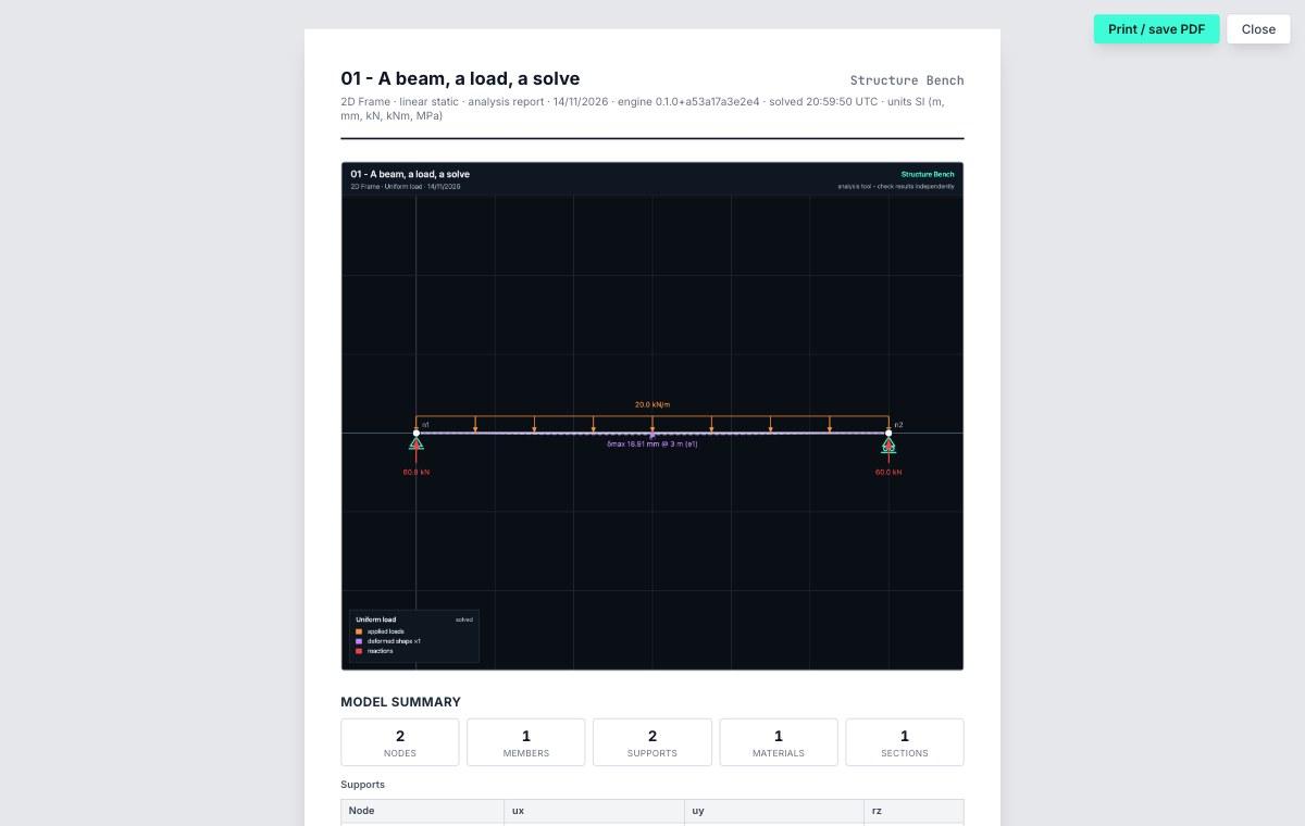
Fig 10. The start of the analysis report for the simply supported beam.
Sharing. Once a model is saved, you can share it with a link. Whoever opens the link sees the model and its results in a read-only view, so it's a handy way to send a model to a colleague, a lecturer or a fellow student.
Stresses. Structure Bench also calculates the stresses in each member's cross-section, and you can see them painted on the model with the Member stress layer. We didn't dig into that here but you'll find a whole learning pathway on the stress analysis feature here.
Learning pathways. I've mentioned Learning Pathways several times already. If you'd like a structured introduction, the learning pathways are the place to start. They walk you through Structure Bench one step at a time, Fig 11. Each step has a live model and explains the engineering behind what you're looking at. The beams and the truss in this guide come from the 2D Beams and frames pathway, and the space truss and building frame come from 3D Beams and frames.
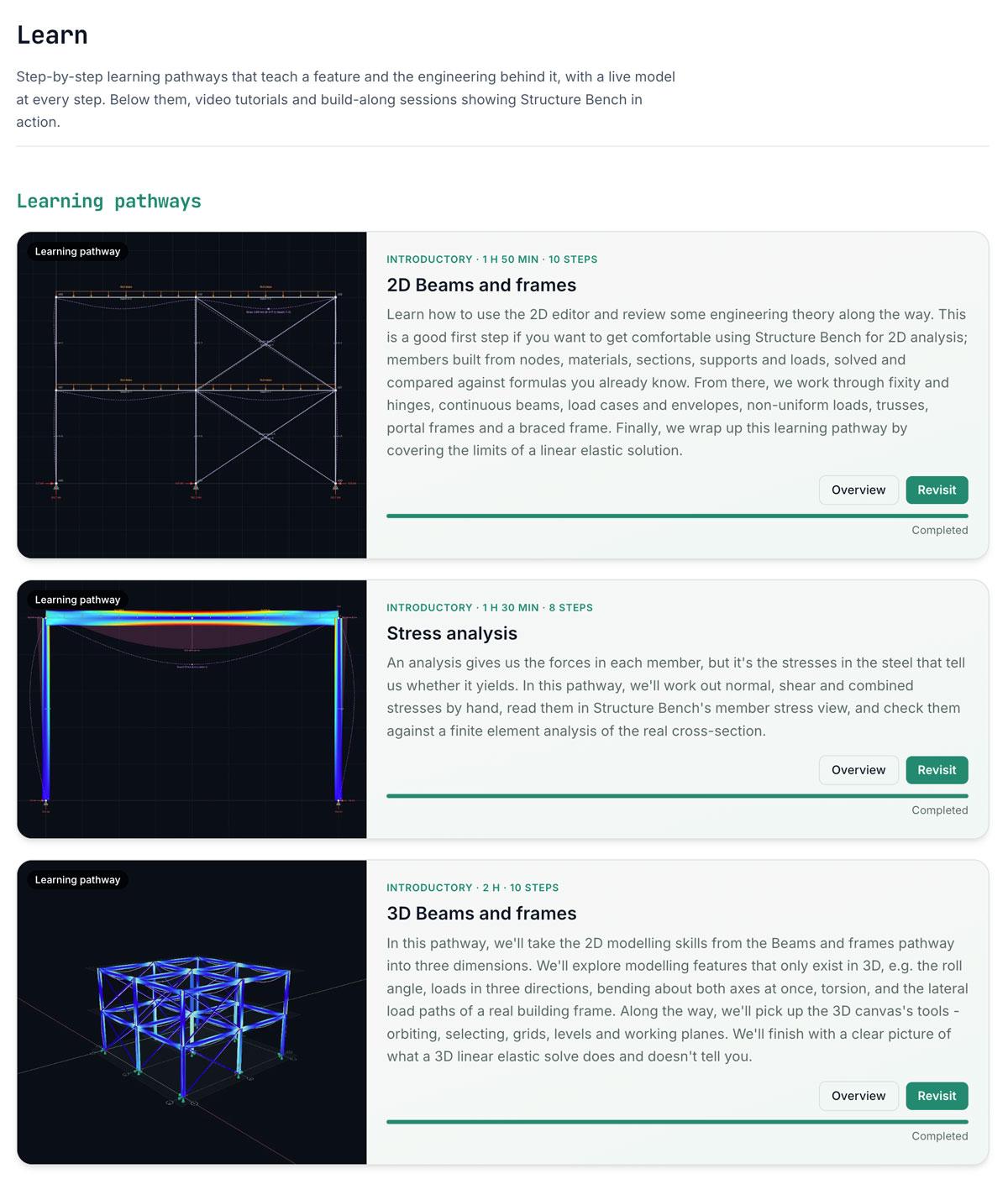
Fig 11. The learning pathways teach Structure Bench and the engineering behind it, with a live model at every step.
6.0 What a linear analysis doesn't check
Before you rely on the results of any analysis, it's important to know what it assumes. Structure Bench's 2D and 3D solvers perform a linear static analysis, and this comes with some baked-in assumptions. Nonlinear analysis will shortly be available for members (these features may be live, depending on when you're reading this).
The analysis is linear, so if you double the load, every result doubles. It's elastic, which means ductile materials (structural steel typically) never yields. So, a member is reported with its full force whether its section can actually resist that force or not. And it's first order, which means the loads act on the undeflected structure. This is the right approach when the deflections are small, but it ignores the extra moments that compression forces cause as the structure deflects.
A linear solve doesn't check for buckling. A slender truss member or column can be reported carrying a compression force well above what it could actually resist before buckling. So, remember, always take a little extra time when dealing with members in compression. Structure Bench also doesn't carry out design code checks - it's strictly an analysis tool. It gives you the forces, moments and deflections, checking compliance with design codes remains your job.
Whatever software you use, you should always try to relate the results back to some form of manual approximation, as we've done throughout this brief introduction. It won't always be as easy as it was for our examples, but even a rough check or approximate analysis will catch many modelling errors.
7.0 What EngineeringSkills members get
Structure Bench is a core part of an EngineeringSkills membership. Membership removes the model size limit, so you can analyse much larger structures. It also opens the advanced features, and we're adding to these all the time.
7.1 Parametric modelling and studies
As a member, you can shortly turn any number in your model into a parameter, such as a span, a depth or a load. On the parametric modelling canvas, parameters and the results you want to track are nodes that you connect to the model with wires (classic node-based workflow). Then you can run a study that solves the model many times over a range of parameter values, Fig 12.
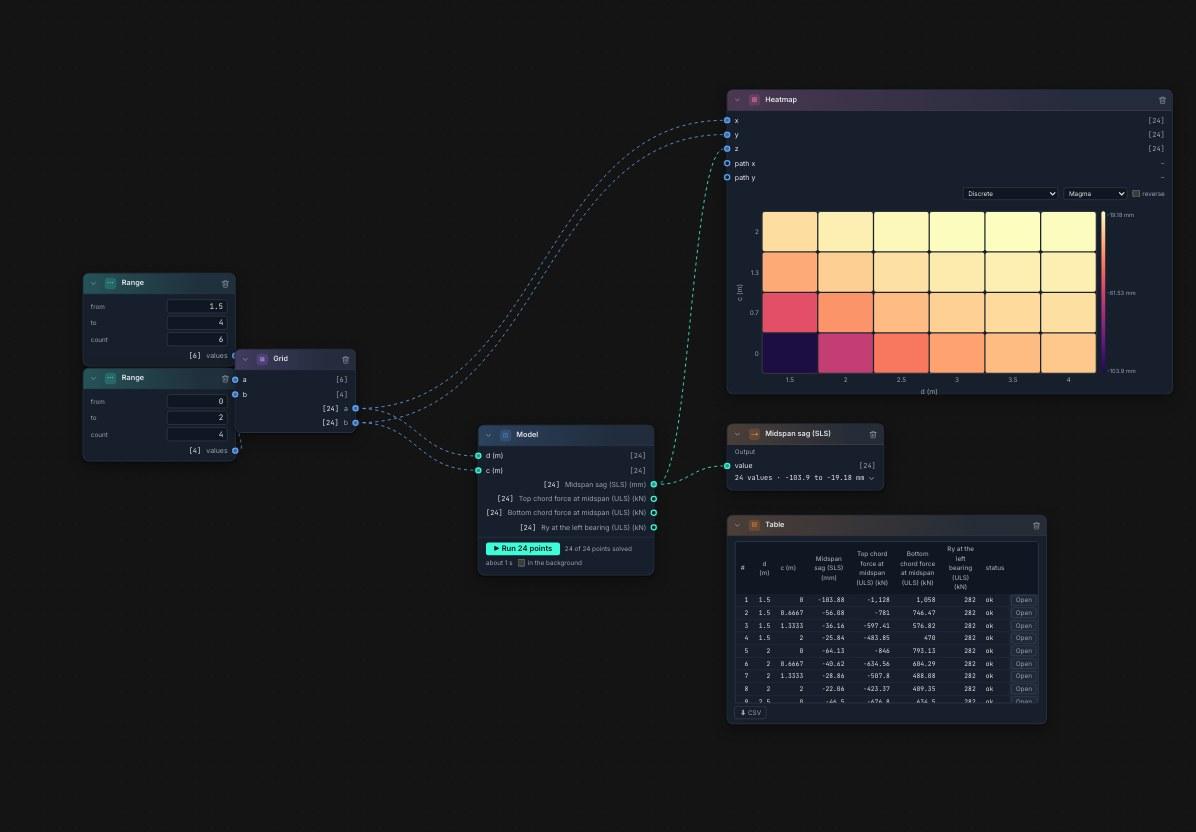
Fig 12. A study on the parametric modelling canvas. Two ranges of truss depth and camber are combined into a grid of 24 points, and the midspan deflection of each is plotted as a heatmap (top right) and listed in a table (bottom right).
The study in Fig 12 is on a parametric truss. It combines six depths between 1.5 m and 4 m with four cambers between 0 and 2 m, which gives 24 versions of the truss. Structure Bench solves all 24 and plots the midspan deflection of each as a heatmap. The deflection ranges from 103.9 mm for the shallowest truss with no camber down to 19.2 mm. Answering a question like this, one model at a time could take an afternoon, depending on how efficient you modelling workflow is. But the study only takes a second or two.
7.2 The Calc sheet
The Calc sheet is another major feature that may be live by the time you're reading this. This is a Python notebook that sits beside your model, Fig 13. It can read your model's parameters, section properties and results directly, so you can write a design check or a calculation record in the same place as the analysis. It gives you full Python API access to your live model. In Fig 13, the sheet reads the design moment of 50.9 kNm from the model, works out the elastic bending resistance of the section, and reports a utilisation of 0.41. When you change the model and solve again, you can re-run the sheet and every value updates.
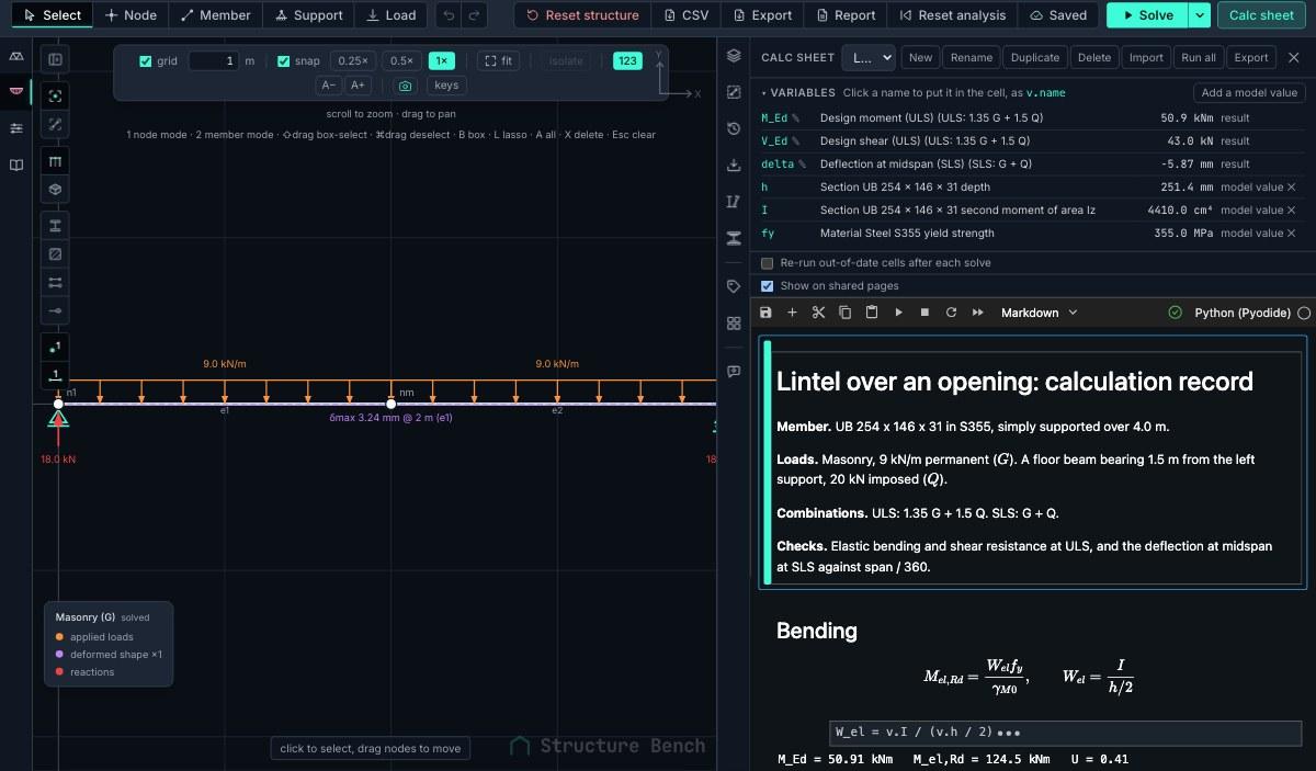
Fig 13. The Calc sheet (right) reading the design moment, shear and deflection from the model (left) for a lintel calculation record.
7.3 Coming soon
I'm also building more advanced analysis types for members. Second-order analysis will capture the effects of geometric non-linearity, which is exactly the effect a first order analysis ignores (section 6). Buckling analysis will find the load at which a structure becomes unstable, and the shape it buckles into. Along with Structure Bench, members obviously get unlimited access to every EngineeringSkills course and tutorial, including the courses linked throughout this guide.
8.0 Getting started
In this guide, we've used Structure Bench as a free truss calculator and a free beam calculator, and then solved some relatively simple structures. The best way to get to know Structure Bench, though, is to use it. Open the free 2D editor or 3D editor and build one of the structures in this guide from scratch, or open its model from the library and change it. Try moving a support, changing a section or adding a hinge, and see if you can predict what will happen before you press Solve.
If you'd like to save your models, sign in with a free EngineeringSkills account. And when you're ready to analyse larger structures, run parametric studies or write calculations beside your model, become an EngineeringSkills member.
All Access Membership
Learn, revise or refresh your knowledge and master engineering analysis and design
Access Every Course and Tool
- Unlimited access to Structure Bench - online analysis platform
- Over 1178 lectures & over 244 hours of HD video content
- Access member-only 'deep dive' tutorials
- Access all downloads, pdf guides & Python codes
- Access to the StructureWorks Blender addon
- Packed development roadmap of courses & tutorials
- Price Guarantee – avoid future price rises as we grow
- Priority Q&A support
- Course completion certificates
- Early access to new courses
Dr Seán Carroll's latest courses.



Featured Tutorials and Guides
If you found this tutorial helpful, you might enjoy some of these other tutorials.
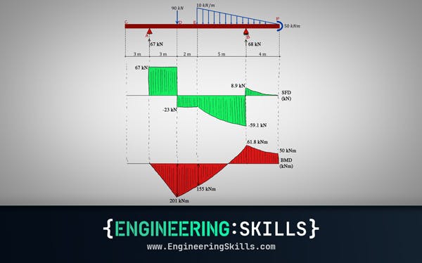
Shear and Moment Diagrams – An Ultimate Guide
[Updated] A thorough introduction to shear forces, bending moments and how to draw shear and moment diagrams with worked examples.

Dr Seán Carroll