A primer on the form and behaviour of gridshell structures
![[object Object]](/_next/image?url=%2Fimages%2Fauthors%2Fsean_carroll.png&w=256&q=75)
First steps towards understanding gridshells
In this article, we’ll begin our exploration of gridshell structures. This will be the first of several such gridshell explorations we’ll make over the coming months here on EngineeringSkills.
Our overall aim is to build up step-by-step,
- an appreciation for these elegant structures and their contribution to the built environment
- an understanding of how they behave under load
- and ultimately, how to form find and analyse them numerically
Here, we’re taking our first steps, and so let’s set ourselves some modest objectives! We will start by,
- referencing some of the iconic gridshell structures
- we’ll discuss actively bent or strained gridshells versus unstrained gridshells
- from here, we’ll move on to a review of the role of form finding in gridshell design
In some respects, this article can be considered a review of the landscape, where we identify the main features to provide a suitable context for further study.
With a good map of the landscape, we can make better decisions about where to explore next. Before too long, we’ll be moving from a narrative discussion into coding and analysis!
What is a gridshell?
A gridshell is a 3-dimensional shell structure similar to a solid shell, wherein the structure is discretised into linear or approximately linear elements meeting at nodal points, Fig 1.
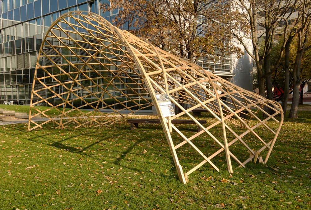
Fig 1. Gridshell pavilion from the Studio of Membrane Architecture, at the CTU campus in Prague, [1]
Gridshells share the same load-resisting mechanism as solid shells in that they derive their ability to resist transverse loads from their double curvature. In this way, the (grid)shell’s ability to and efficiency in resisting load is inextricably linked to its form or shape.
Therefore, gridshell design is a two-step process: first, a suitable form is established through physical or numerical modelling. Then, service loads are applied to this form to determine its ability to resist these loads in service.
Membrane Action and Bending
Under theoretically ideal conditions, a gridshell will develop exclusively axial stresses through membrane action. However, practically speaking, this is not achieved since variations in applied service loading, the need to provide edge restraint and aesthetic considerations will almost always give rise to localised bending and shear within the gridshell. Having said this, the design objective should be to utilise membrane action to the greatest extent possible.
Early work on gridshells
There is a rich history of shell and gridshell pioneers going back to the mid-20th century: Heinz Isler, Félix Candela, Ove Arup, to name just a few. In fact, as early as the late 19th century, the Societ Russian engineer Vladimir Shukhov designed and oversaw the construction of a steel gridshell in Vyksa near Nizhny Novgorod. This can be seen in the well-known photographic reproduction, Fig 2.
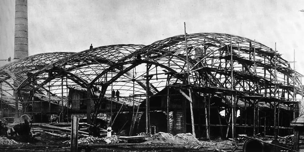
Fig 2. Photographic reproduction of Vladimir Shukhov’s steel gridshell in Vyksa (1897), [2]
This study and development of gridshell structures continues at pace today with contemporary engineers and researchers continuing to provide insight into their analysis and design. Today’s big names include Sigrid Adriaenssens, John Ochsendorf, Chris Williams and Mike Barnes, again to name just a few of the many hundreds of active contributors to this space.
There is undoubtedly a great history of structures course out there somewhere that charts the evolution of gridshells far better than I can!
So, to get a flavour of the heritage of these structures, we focus on the early work of Frei Otto (1925-2015) - one of the giants of form-found structures. This will give us a sense of the origin story of gridshells.
Otto was actively working in architecture and engineering from the 1950’s to the 1990’s. His achievements extend far beyond gridshells into tensile and membrane structures. An excellent review of Otto’s work was written by Philip Drew in his book Frei Otto, Form and Structure [3]. Many of the observations in this article are drawn from this text—it’s well worth seeking out.
If you want to get a broader sense of Otto’s contributions to Architecture and Engineering, the 2016 documentary, Spanning the Future, is fantastic.
Frei Otto’s gridshells
Some of Otto’s earliest explorations into gridshell structures were quite modest by comparison to his opus, the Mannheim Multihalle gridshell, completed in 1974.
Essen Gridshell, 1962
Much earlier, in 1962, for example, he erected a much simpler timber gridshell at the German Building Exhibition in Essen, Fig 3.
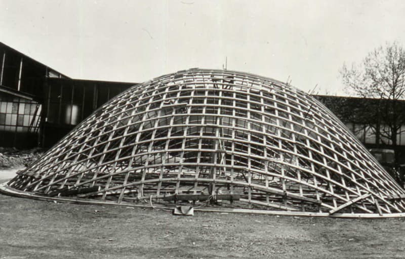
Fig 3. The timber gridshell at Essen being raised into position [3].
The structure was originally set out in a planar lattice or grid measuring . This was gradually raised into position to assume the final shape. The construction and erection sequence involved:
- Assembling the timber lattice, flat on the ground.
- Intersections (nodes) between the timber laths were loosely connected with bolts
- A crane was then used to raise the lattice incrementally into its dome-like shape.
- Once in position, the ends of the laths were connected to the perimeter beam and the bolted joints were tightened.
- The gridshell was stiffened with additional ropes, further locking it into shape.
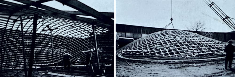
Fig 4. The gridshell under construction, propped from below (left) and the lattice being raised into position by a mobile crane (right) [3].
This, at the time experimental, gridshell demonstrates some of the fundamental features of a gridshell structure; the unique erection process and the “locking in place” by making joints rigid and fixing boundaries into position. This process of “raising the structure” into its final position is still used today.
The erection of the Essen dome was actually the final step in a longer form study on the shape of the structure. During his form finding (discussed below), Otto built both hanging chain and scale models of the structure to try and predict the form that would emerge from the erection process. Both of these techniques remain central to form finding studies today—although much greater use is now made of numerical models.
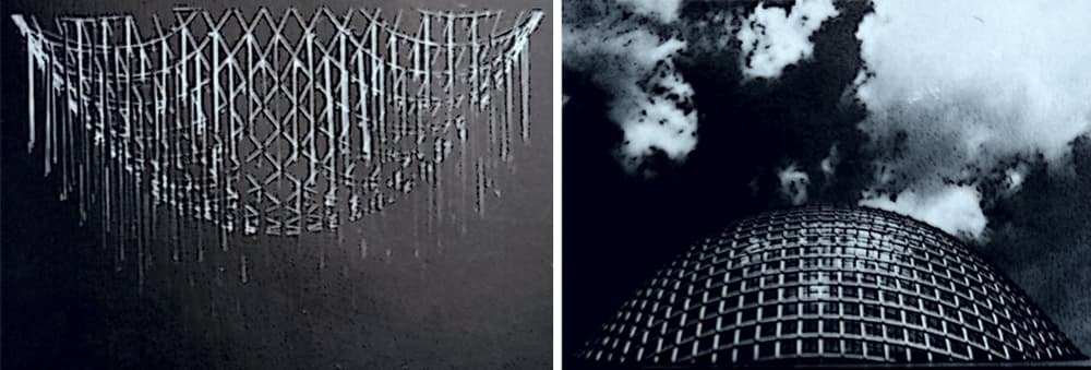
Fig 5. Hanging chain model (left) and 1:20 scale timber model (right) [3].
Berkeley, 1962
That same year, while at The University of California, Berkeley, Otto continued his experimentation with lattice structures - this time constructing a gridshell from steel rods, Fig 6.
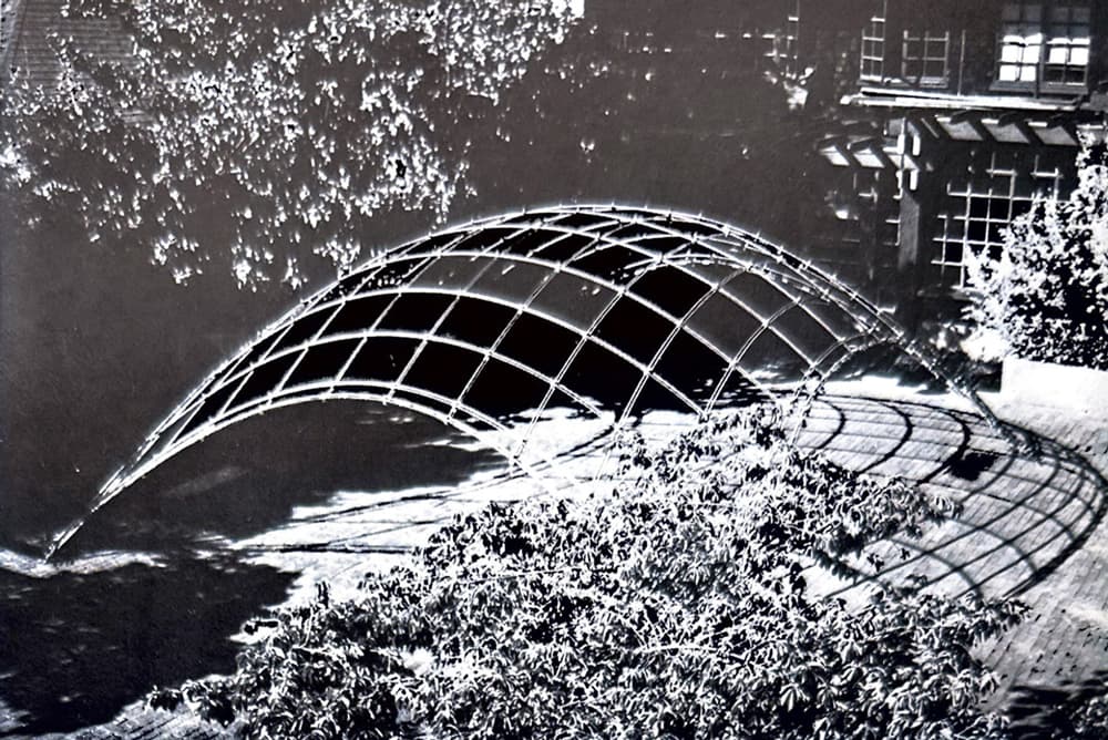
Fig 6. Steel rod gridshell at The University of California, Berkeley, 1962 [3].
Otto again made use of hanging chain nets to investigate the optimal shape for the structure. Both the material and form of the full-scale structure mean that it bears a striking resemblance to the scale models.
It’s worth noting however, that the full-scale structure is formed by flexing continuous rods - this leads to fundamentally different structural behaviour to that observed from the linked-chain hanging nets. Despite this, the geometry of the latter can still be used to guide the former, as we’ll see below.
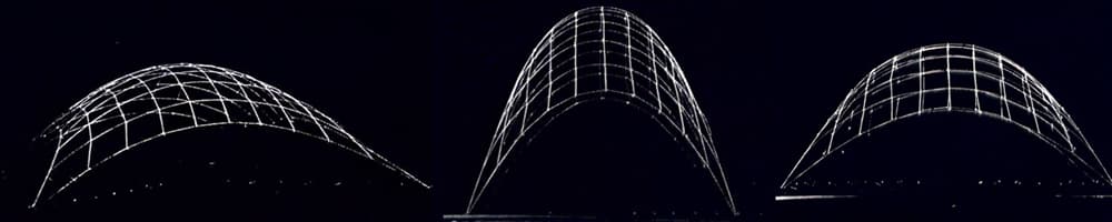
Fig 7. Suspended (shown inverted) chain model studies of the Berkeley gridshell [3].
In contrast to the Essen structure, note that in the Berkeley gridshell, the structure only has four points of support versus the continuous ground beam observed at Essen. The immobility of the perimeter or ground beam is typically central in achieving and maintaining the gridshell shape. Without this, the Berkeley gridshell relied exclusively on the locking of joints to maintain its form.
The Mannheim Multihalle Gridshell (1970-1974)
From Essen and Berkeley in 1962, we jump forward to 1970 and to arguably one of the greatest examples of large-scale gridshell construction, the Mannheim Multihalle Gridshell, conceived, designed and built between 1970-1974.
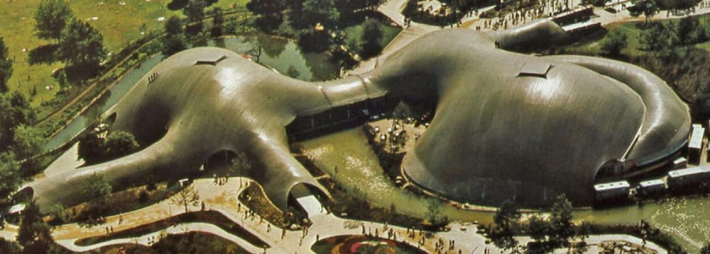
Fig 8. The Mannheim Multihalle Gridshell [4].
This enormous structure has a curved surface area of . Otto was the architect for this project and as such, was one part of a large team including engineers Bräuer and Späh and Ove Arup and Partners.
Ian Liddell, part of the original design team, has produced an excellent case study [4] on the design and construction of the project. This can be freely downloaded here and is a relatively rare first-hand account of the development of such an iconic, and now relatively old structure.
Of particular relevance to our discussion is the elaborate hanging chain model that was used to define the geometry of the structure. Liddell reports that,
The ends of the link lines were connected to the boundary line with small springs that could be adjusted to achieve a reasonably uniform tension in the grid.
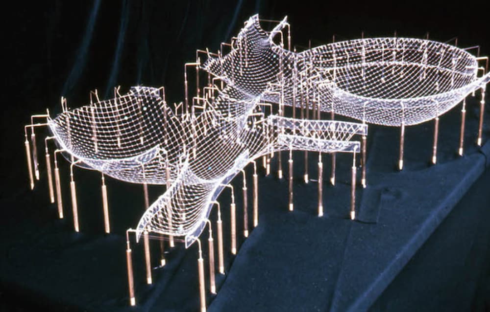
Fig 9. The hanging chain model used to define the geometry of the Mannheim gridshell [4].
The erection of the Mannheim gridshell used the same techniques that Otto has experimented with in Essen over a decade earlier; the grid, consisting of straight continuous ribs, was originally laid out flat and post-formed by imposing displacements on the gridshell boundaries.
The in-plane shear stiffness of the structure was enhanced by triangulating the quadrilateral timber grid with steel cables. This remains a common practice, typically required when the gridshell is required to resist additional superimposed loads beyond its own self-wight.
The Mannheim Multihalle and other early gridshell structures continue to provide inspiration to the many thousands of architects and engineers that have followed Frei and his fellow early pioneers. With these examples as our motivation, let’s now consider some of the more technical aspects of gridshell behaviour.
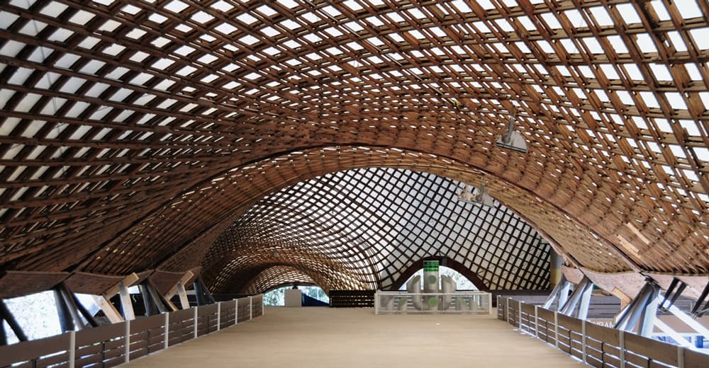
Fig 10. View from inside the Mannheim Gridshell [5].
Actively Bent or Strained versus Unstrained Gridshells
There are two distinct flavours of gridshell - the actively bent or strained gridshell and the unstrained gridshell. They are quite different in terms of how they are designed and built. We consider each in turn.
Actively bent gridshells
Actively bent gridshells are formed by bending continuous straight laths into their final shape. This bending into shape induces stresses in the structure - leading to the actively bent designation. All of Otto’s gridshells discussed above are actively bent gridshells.
The bending into shape is achieved by starting with a flat square grid of (usually timber) strips or laths, loosely connected at intersecting points. The laths are free to rotate in-plane relative to each other. The grid is then raised into position.
When the gridshell has been raised to the desired shape, supports are restrained and in some cases the joints may be locked or made rigid, stopping the gridshell from settling back into its original flat position, as described above.
To increase the in-plane shear stiffness of the gridshell, diagonal cables or timber struts can be used to brace the structure, Fig 11. Since the gridshell can only resist in-plane forces along the lines of the laths, these bracing elements are needed to allow the gridshell to approach the in-plane resistance seen on solid shells.
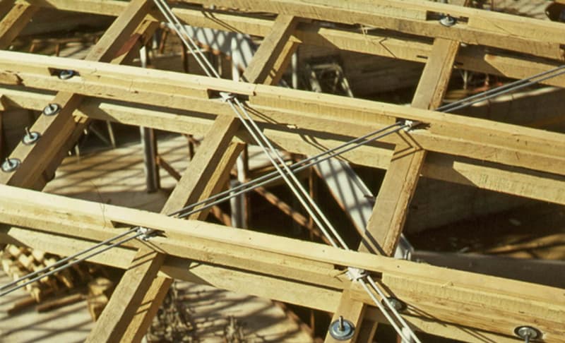
Fig 11. Diagonal cable bracing in the Mannheim gridshell [4].
To increase the out-of-plane bending resistance of the gridshell, multiple grid layers may be used - provided that the layers are free to slide relative to each other during erection. When sufficient packing is provided between the layers, they will act compositely, significantly increasing the gridshells bending resistance.
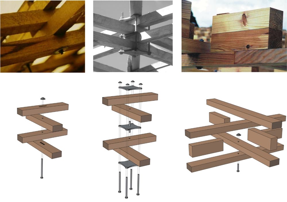
Fig 12. Three different double layering techniques showing connection details; slotted hole (left), clamping plate (middle) and shear block (right) [6].
The key thing to appreciate with actively bent gridshells is that they have a level of bending stress baked-into the structure—thus there is a baseline of stress present before the application of any service loading.
The nuance here is that the identification of a suitable form is dependent on the flexural rigidity of the laths.
Form finding can, therefore, not be purely a geometric exercise but must result from an elastic analysis.
This is why Otto used both a hanging chain and scale timber model when researching his Essen gridshell—the hanging chain informed the optimal geometric surface while the influence of the model lath bending resistance mimicked the full-scale structural behaviour.
Aesthetically we can recognise actively bent gridshells by their smooth flowing lines and relatively simple nodal points.
Unstrained gridshells
By contrast, unstrained gridshells do not have forming-stresses baked in. They are constructed from linear or pre-curved elements that meet at nodal connectors. Geodesic domes fall within the family of unstrained gridshells. Visually, unstrained gridshells are noticeably different to strained gridshells, recognisable by their linear edges and faceted planar surfaces.
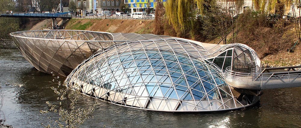
Fig 13. Murinsel gridshell by Vito Acconci, Graz [7].
Unstrained gridshells are typically constructed element-by-element with nodal connections providing the direction change between individual linear elements.
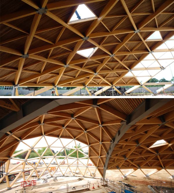
Fig 14. Unstrained gridshell roof at The Pods sports academy, Scunthorpe [8]
Since unstrained gridshells are not limited to the organic (and optimal) shapes that emerge from raising the flat grid into position - they are free to adopt almost any required shape. This freedom to adopt a wider variety of shapes has led to the term freeform being used to describe such shells. As a result, the shape of unstrained freeform gridshells is driven by aesthetic, architectural and construction considerations to a far greater degree than actively bent gridshells.
Unstrained gridshells are more complex (in their connections) and, therefore, more costly to manufacture. The geometry of the gridshell usually means that these are unique across the structure, inflating their cost.
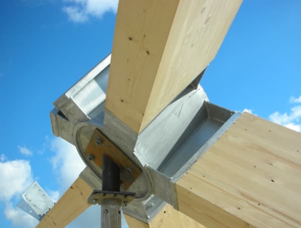
Fig 15. Nodal connection from The Pods gridshell [8]
On the other hand, they benefit from the speed and efficiency of offsite manufacturing. The erection process is also more straightforward since the complete structure does not need to be raised and stressed in a single operation.
The resulting faceted surface can also lead to more straightforward cladding or glazing since the gridshell surface consists of planar panels rather than a continuously curving surface.
Form finding
We have already said that the ability of a shell to resist loading is directly related to its shape or form, particularly in the case of a strained gridshell. As a result, a process known as form finding must be completed, which involves identifying the optimal shell geometry for a given set of loading and boundary conditions.
There are various form finding methods but they all have the same underlying objective, to identify the surface shape that minimises the strain energy in the structure while force balance is maintained between internal and external forces. The shell boundary conditions must also be respected and are a key ingredient in the form finding process.
The Funicular Form
Funicular forms refer to the bending-free forms that are adopted when structures, typically cables, chains or nets, are subject to some loading. The term funicular means tension only or compression only for a given loading. We explore funiculars in more detail in our graphic statics tutorial.
The most familiar funicular form is the catenary, the shape that a hanging cable or chain makes under gravity loading. Since the chain only experiences tension while hanging, and not bending, if we invert the catenary, we obtain an arch in pure compression. The arch shape is said to be a funicular for self-weight loading, Fig 16.
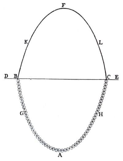
Fig 16. Hooke’s hanging chain (pure tension) and mirrored arch (pure compression), as depicted by Poleni, 1748. Reproduced here from [9].
This is often referred to as Hooke’s principle after the English engineer Robert Hooke (1635-1703). This shouldn’t be confused with Hooke’s law - also coined by Robert Hooke.
Physical models (hanging chain models)
The 2D hanging chain can be expanded to three dimensions in the form of a hanging chain net. The same funicular principle also extends to 3D; a hanging net in pure tension, when inverted, reveals the shape of a pure compression (membrane) shell - but again, only for the specific case of gravity loading.
Non-linear Finite Element Analysis of 2D Catenary & Cable Structures using Python
Build an iterative solution toolbox to analyse structures that exhibit geometric non-linearity due to large deflections.
After completing this course...
- You will understand the concept of geometric non-linearity and when it should be considered.
- You will understand how to modify the axially loaded element stiffness matrix to account for large deflections and changes in geometry.
- You will have implemented a Newton-Raphson iterative solution algorithm that seeks to converge on the deformed state of the structure.
- You will have a workflow that leverages open-source modelling tools in Blender to quickly generate the initial structural geometry.
This observation led to the first practical form-finding techniques that employed hanging chain models to identify funicular shell forms. As we’ve seen above, Otto and others used this technique extensively to identify optimal membrane shapes with Otto’s elaborate hanging chain model of Mannheim perhaps being one of the most well-known examples, Fig.9 above.
A hanging chain model will adopt a funicular form which, it must be remembered, by definition, is associated with a single loading arrangement. In form studies, this is typically gravity loading. Thus, the prediction of pure membrane action in the corresponding (grid)shell, only holds for self-weight and is intolerant of geometric imperfections and loading variations in the real structure. As such, joints must also resist moments to provide buckling resistance to the real-world shell.
Hanging chain models and the related soap-film technique, also employed by prominent early pioneers, can be considered purely geometric approaches to form-finding. That is, they don’t capture the influence of the gridshell’s bending stiffness on the found shape. Furthermore, they cannot provide any information on the stresses that develop in actively bent shells during erection. For this, we turn to numerical models.
Materially accurate scale models are also employed to capture the influence of element stiffness on the gridshell shape identified through form-finding (see Essen). One contemporary example is the Trio gridshell in Lecce, Italy 2010, excellently documented by Bernardino D'Amico in his Masters Thesis [10].
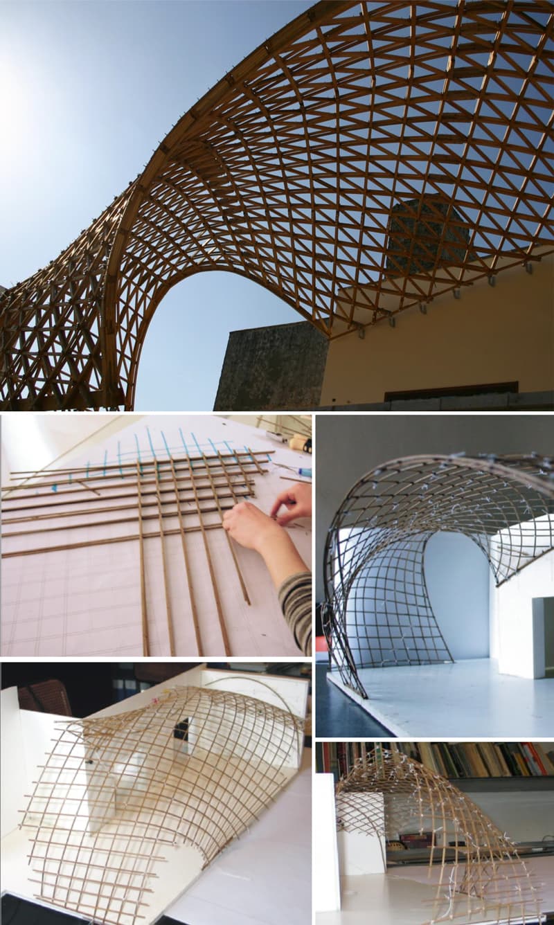
Fig 17. Full-scale timber gridshell (top) and collection of model images (bottom 4) [10].
Computational approaches
Physical form-finding models still have an important role in the design of gridshell structures. They can provide valuable insight into the anticipated gridshell shape and act as a sanity check to numerical analysis.
A physical model will almost always be directionally correct, even if the accuracy is somewhat limited by the fidelity and scale of the model. In contrast, computational models have the potential to provide wildly inaccurate results due to programming and other simulation errors.
Having said that, the ease with which one can identify minimum energy surfaces with complex loading and boundary conditions through simulation means that numerical analysis has become the de facto technique for lightweight structure form finding.
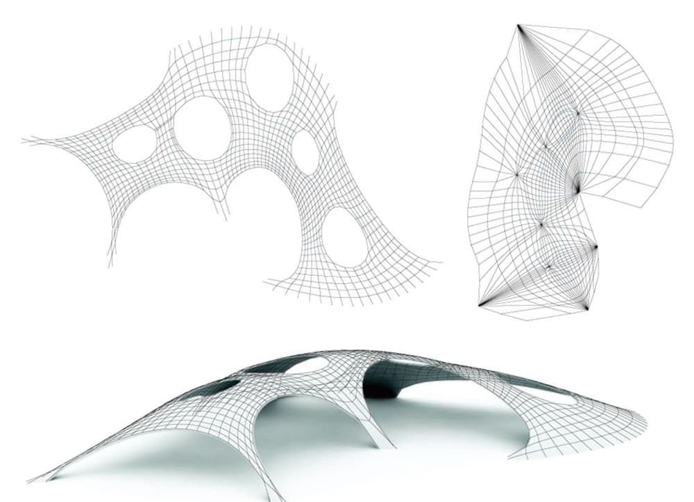
Fig 18. Compression-only funicular form, obtained using Thrust Network Analysis method. [11].
Numerical approaches afford us the ability to explore many more parameters and initial configurations than would be feasible with scale modelling. Some algorithms also allow us to identify the baked-in stresses developed in actively bent shells as a natural output from the simulation. One such algorithm is Dynamic Relaxation - probably the most widely used technique, originally developed by Alistair Day in 1965.
Dynamic Relaxation and non-linear finite element analysis
For an actively bent gridshell, numerical form finding through dynamic relaxation involves simulating the erection process to identify the final settled position of the structure and the associated stresses induced. To do this, we need as inputs,
- The undeformed and unstressed grid shape, often termed the cutting pattern. This takes the form of a flattened or planar square grid or mat.
- The displacements that will be imposed to force the mat into the desired shape. This vector of displacements may be boundary displacements - in this case the shell can be thought of as being pushed up into its final shape by the displacement of the boundaries. This mimics the actual construction process. The initial boundary displacements can be conveniently obtained from scale model testing. Alternatively, the mat can be allowed to deflect under a fictitious gravity load with suitable boundary conditions respected.
A variation of this simulation approach involves the use of a reference surface to guide the final shape of the gridshell. In this method, the initially flat mat is bent to match the reference surface using spring forces.
Once the mat has deformed to match the reference surface, its perimeter nodes are restrained and the spring forces are disabled. This allows the mat to settle to a new equilibrium minimum energy position that closely approximates the reference surface. Since the reference surface guides the shape of the gridshell, there is no need to specify the cutting pattern or boundary displacements.
The numerical form finding outlined above requires us to evaluate the force distribution in the structure at each timestep. One of the most convenient tools for the job is finite element analysis. However, the very large deformations involved in the form-finding process result in geometrically non-linear behaviour. So, an iterative non-linear analysis is called for. This is where dynamic relaxation enters the picture.
The form-finding procedure and its application to gridshell structures is explained by Andriaenssens and Barnes in their seminal 2001 paper [12]. We’ll save the details of its implementation for a future tutorial but outline the basic idea here.
Dynamic relaxation treats the geometrically nonlinear problem like a dynamic analysis. The motion of each node in the system, under the influence of the applied loads, is simulated over successive time increments until the system comes to rest in equilibrium. A viscous damping force (or kinetic damping) is introduced to the analysis such that the system does eventually converge to within an acceptable tolerance.
Once the structure has converged, an optimal surface for the given boundary conditions and applied loads has been obtained. The benefit of this numerical scheme is that the internal member forces required to maintain equilibrium can be reported directly from the model. We’ll explore the technique in detail in a future EngineeringSkills project.
Freeform gridshells
All of our discussion on form finding up to this point has focused on actively bent shells. However, in addition to practical hanging chain models, there are various numerical methods that yield funicular forms, e.g. the Particle Spring Systems and Thrust Network Analysis, Fig 18 above. We will likely examine these in future tutorials or projects.
As we’ve already mentioned, a freeform (unstrained) shell is exactly that, free to take up any form that the designer conjures up and not necessarily one that emerges from a minimum energy analysis. In addition to the structures we’ve highlighted above, another notable example is the steel roof above the courtyard at the Dutch Maritime Museum, Fig 19.
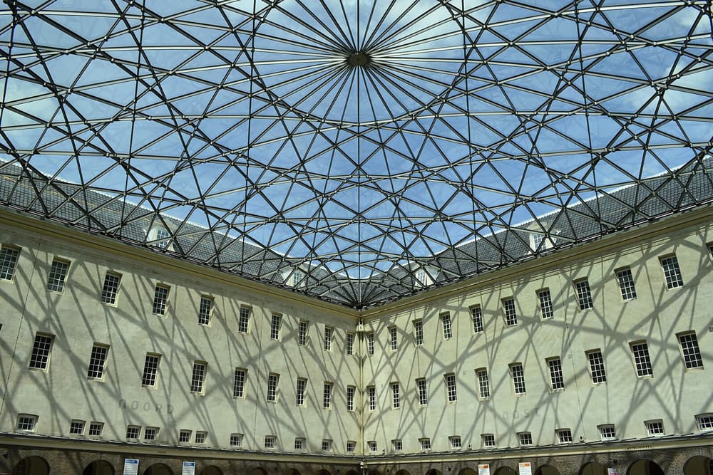
Fig 19. Steel roof above the courtyard of the Dutch Maritime Museum [13].
This is an example of a shell where aesthetic and symbolic considerations drove the structural form. The steelwork arrangement covers a plan area of and was inspired by compass rose lines on old nautical charts, Fig 20.
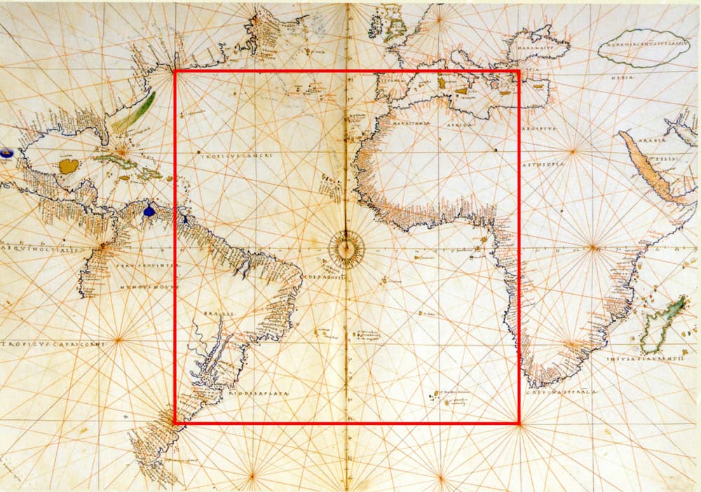
Fig 20. The compass rose lines that inspired the steelwork arrangement of the steel shell above the Dutch Maritime Museum, as shown on the project architect's website, Ney + Partners [14].
Next steps
We set out at the start of this article with the goal of developing a better understanding of gridshell structures; their origins, how they work and how their forms are found through experimentation and analysis. Hopefully, you feel like we’ve gone some way towards accomplishing this.
So, what next? To deepen our understanding of the topics discussed above, we really need to explore the analysis techniques firsthand. So, in our next gridshell tutorial, we’ll set about building a workflow for modelling and analysing our own gridshell structures.
In our next installment, we’ll start by considering unstrained gridshells. This will give us a good foundation on which to build our own dynamic relaxation algorithm for actively bent gridshells a little further down the line.
Plenty more to come!
[1] Wikipedia
[2] Wikipedia
[3] Philip Drew, “Frei Otto, Form and Structure”, Westview Press, 1976
[4] Liddell, I. “Frei Otto and the development of gridshells”, Case Studies in Structural Engineering, 4 (2015) 39-49
[5] Wikipedia
[6] D’Amico, Bernardino, Timber Grid-shell Structures: form-finding, analysis and optimisation, PhD Thesis, Edinburgh Napier University, 2015
[7] Wikipedia
[8] Harris, R, Gusinde, B & Roynon, J 2012, 'Design and construction of the pods sports academy, Scunthorpe, England', Paper presented at World Conference of Timber Engineering 2012, Auckland, New Zealand, 16/07/12 - 19/07/12 pp. 510-517.
[9] Adriaenssens et al. “Shell Structures for Architecture, Form Finding and Optimisation”, Routledge, 2014
[10] B. D’Amico. Design and building of a post-formed timber gridshell. Master’s thesis, University of Naples Federico II, Italy, 2010
[11] M. Rippmann, L. Lachauer, and P. Block. Interactive vault design. International Journal of Space Structures, 27(4):219–230, 2012
[12] S. Adriaenssens and M. Barnes. Tensegrity spline beam and grid shell structures. Engineering structures, 23(1):29–36, 2001
[13] Wikipedia
[14] Ney + Partners

Dr Seán Carroll's latest courses.


Featured Tutorials and Guides
If you found this tutorial helpful, you might enjoy some of these other tutorials.

Understanding Tresca and von Mises Elastic Failure Theories
Go from the fundamentals of elastic failure theory to implementing section analysis in Python using sectionproperties

Julian Haudek
